- Mammoth Grip Sprinkler Spacers. Mammoth Grip Sprinkler Spacers are used to stabilize and accurately install sprinkler heads.
- Armada Technologies Pro48 Solenoid Activator / Chatterbox and Pro210 Tone Probe. Portable, irrigation system tester. Activates valves, tests solenoids, tests wire continuity, chatters solenoids, and has a tone generator for wire identification.
- Sprinkler Buddy Sprinkler Head Indicator. The Sprinkler Buddy keeps grass from growing next to or over the sprinkler head, thus make the sprinkler location obvious in the lawn.
Category Archives: Questions and Answers
Irrigation Controller or Timer Reviews
Key to common controller features in the table below:
- Stations. Maximum number of valve stations. The actual number of stations may be less depending on which model is purchased. In most cases you need one station for each automatic valve.
- Programs. Number of programs available. Each program can have different start times, operation days, and run times for the irrigation valve stations. You need to use different programs for areas with different water requirements. For example a lawn might need to be watered every other day, but drought tolerant shrubs might need watering only once a week or less. Without separate programs they would both be watered on the same days and the shrubs might drown. More programs allows more flexibility resulting in water savings and healthier plants. Most homes need at least 2 programs, one for the lawn and one for the shrubs. Few homes need more than 4 programs.
- Smart Controller. A “Smart Controller” adjusts the watering schedule by itself throughout the year. Smart controllers are quickly becoming mandatory by law in much of the Western and Southern USA. To read more on Smart Controllers see the Smart Controller FAQ. If the controller has Smart features the following key indicates what system is used:
- H Historical. Adjusts watering based on historical water use records.
- HS Historical with a sensor. Fine tunes historic data using current condition sensor.
- OS Off-site data via phone, radio, Internet, etc.
- WS Weather station. Has it’s own weather station.
- MS Uses a soil moisture sensor.
- Master Valve Has a control circuit for a master valve and/or pump start switch. An important feature if you use a pump.
- Rain Sensor Has a circuit for attaching a rain sensor. Shuts down if rain detected (typically the sensor itself is not included.)
- Non Volatile Memory is non-volatile, retains data without a battery even in a power failure.
- Delay A delay can be programmed between valve stations to allow time for slow closing valves to close fully. Another important feature if you have a pump, or if you have low water pressure.
| Manufacturer/ Product Name Click on Name to Read Review | Part No. | S t a t i o n s | P r o g r a m s | S m a r t C o n t r o l l e r | M a s t e r V a l v e | R a i n S e n s o r | N o n V o l a t i l e | S t a t i o n D e l a y | |
|---|---|---|---|---|---|---|---|---|---|
| Gwytech PC Timer | V 1.0 | 8 | 4 | X | X | X | X | ||
| WeatherTRAK ETplus | WTPLS-06 | 6-48 | 3 | OS | X | X | X |
Automatic Irrigation Solenoid Valves Reviews
This page contains an index and links to reviews of automatic solenoid valves commonly used in landscape sprinkler systems and other irrigation systems.
Electric Anti-Siphon Valves
| Manufacturer | Reviews | Part No. | Description |
|---|---|---|---|
| Champion | CL466-075, CL466P-075 CL466-100, Cl466P-100 | 3/4″ Anti-Siphon Valve 1″ Anti-Siphon Valve | |
| Hunter | Click Here for Review | ASV series | 3/4″ Anti-Siphon Valve 1″ Anti-Siphon Valve |
| Irritrol | Click Here for Review | 2711APR 2713APR 2711DPR 2713DPR | 3/4″ Anti-Siphon Valve 1″ Anti-Siphon Valve 3/4″ Anti-Siphon Valve 1″ Anti-Siphon Valve |
| Irritrol | Click Here for Review | 311A-.75 311A-1 | 3/4″ Anti-Siphon Valve 1″ Anti-Siphon Valve |
| Lawn Genie | Same as Irritrol anti-siphon valves Click Here for Review | L7034 L7010 RJ 3/4 54000 | 3/4″ Anti-Siphon Valve 1″ Anti-Siphon Valve 3/4″ Anti-Siphon Valve |
| Orbit | 57223 57224 | 3/4″ WaterMaster Anti-Siphon Valve 1″ WaterMaster Anti-Siphon Valve | |
| Rainbird | DAS-075, 075-ASVF DAS-100, 100ASVF | 3/4″ Sure Flow Anti-Siphon Valve 1″ Sure Flow Anti-Siphon Valve | |
| Rainbird | APAS-075 APAS-100 | 3/4″ Anti-Siphon Valve 1″ Anti-Siphon Valve | |
| Rain Jet Name changed to Lawn Genie | Same as Irritrol anti-siphon valves Click Here for Review | ||
| Toro Irrigation | 299-0?-03 299-0?-04 | 3/4″ Flo-Pro Anti-Siphon Valves 1″ Flo-Pro Anti-Siphon Valves | |
| WaterMaster (Orbit) | 57223 | 3/4″ Anti-Siphon Valve |
Electric Angle or Globe Valves
| Manufacturer | Reviews | Part No. | Description |
|---|---|---|---|
| Champion | PGA-075 PGA-100 PGA-150 PGA-200 | 3/4″ globe valve 1″ globe valve 1.5″ globe valve 2″ globe valve | |
| Hardie | Hardie is now called Irritrol | ||
| Hunter | Click Here for Review | SRV series | 1″ globe valve |
| Hunter | Click Here for Review | PGV series | 1″ globe valve 1″ angle valve 1 1/2 & 2″ combination globe/angle valves |
| Hunter | Click Here for Review | HPV-101-G HPV-101-A | 1″ globe valve 1″ angle valve |
| Hunter | Click Here for Review | ICV-101-G ICV-151G ICV-201G | 1″ globe valve 1.5″ globe valve 2″ globe valve |
| Hydro Rain (2 separate companies, different products) | (Old) Hydro Rain (of Laguna Niguel, products made pre 2000) these products are now made under the name Irritrol. —- (New) Hydro Rain (of North Salt Lake City, products made from 2005) I have not reviewed the new Hydro Rain branded products yet. | ||
| Irritrol | Click Here for Review | 2400* 2600* | 1″ globe valves 1″ angle valves |
| Irritrol | Click Here for Review | 2500T 2500TF | 1″ globe valve |
| Irritrol | Click Here for Review | 205TF | 1″ globe valve |
| Irritrol | Click Here for Review | 214B 216B 217B | 1″ combination globe/angle valve 1.5″ combination globe/angle valve 2″ combination globe/angle valve |
| Irritrol | Click Here for Review | 100-1 100-1.5 100-2 100-3 | 1″ combination globe/angle valve 1.5″ combination globe/angle valve 2″ combination globe/angle valve 3″ combination globe/angle valve |
| Irritrol | Click Here for Review | 102-1 102-1.5 102-2 102-3 | 1″ DW combination globe/angle valve 1.5″ DW combination globe/angle valve 2″ DW combination globe/angle valve 3″ DW combination globe/angle valve |
| Irritrol | Click Here for Review | 700-.75 700-1 700-1.5 700-2 | 3/4″ globe valve 1″ globe valve 1.5″ globe valve 2″ globe valve |
| Lawn Genie | Same as Irritrol 2500 series Click Here for Review | 54002 54003 54004 54005 | 1″ Globe Valve 1″ Globe Valve 1″ Globe Valve 3/4″ Globe Valve |
| Nelson (L.R. Nelson Corp.) | 7911, 7917 7931 | 1″ globe valve 1″ angle valve | |
| Nelson (L.R. Nelson Corp.) | 7951, 7971 | 1.5″ combination globe/angle valve | |
| Nelson (L.R. Nelson Corp.) | 7952, 7972 | 2″ combination globe/angle valve | |
| Nelson (L.R. Nelson Corp.) | 7953, 7973 | 3″ combination globe/angle valve | |
| Rainbird | JTV | 1″ globe valve (jar top) | |
| Rainbird | CP Series | 3/4″ & 1″ globe valves | |
| Rainbird | CPF Series | 3/4″ & 1″ globe valves | |
| Rainbird | 075-DV, 100-DV, 100-DV-SS, 100-DV-A, 100-DV-MM, 100-DV-MB, 125-DV-MB | 3/4″ & 1″ globe valves | |
| Rainbird | 100-DVF, 100-DVF-SS 100-DVF-A, 100-DVF-BSP | 1″ globe valve | |
| Rainbird | 100-PGA, 100-PGA-BSP 150-PGA, 150-PGA-BSP 200-PGA, 200-PGA-BSP | 1″ combination globe/angle valve 1.5″ combination globe/angle valve 2″ combination globe/angle valve | |
| Rainbird | 100-PEB, 100-PEB-BSP 150-PEB, 150-PEB-BSP 200-PEB, 200-PEB-BSP | 1″ globe valve 1.5″ globe valve 2″ globe valve | |
| Rainbird | 100-PESB, 100-PESB-BSP 150-PESB, 150-PESB-BSP 200-PESB, 200-PESB-BSP | 1″ DW globe valve 1.5″ DW globe valve 2″ DW globe valve | |
| Rainbird | GB Series Brass Valves | 3/4″ globe valve, 1″ globe valve, 1 1/4″ globe valve, 1 1/2″ globe valve, 2″ globe valve | |
| Rainbird | EFB-CP Series Brass Valves | 3/4″ globe valve, 1″ globe valve, 1 1/4″ globe valve, 1 1/2″ globe valve, 2″ globe valve | |
| Richdel | Richdel is now called Irritrol | ||
| Superior | Click Here for Review | 950 & 950RW Brass Valves | 3/4″ globe valve, 1″ globe valve, 1 1/4″ globe valve, 1 1/2″ globe valve, 2″ globe valve |
| Superior | Click Here for Review | 1000 series Brass Valves for Recycled Water | 3/4″ globe valve, 1″ globe valve, 1 1/4″ globe valve, 1 1/2″ globe valve, 2″ globe valve, 2 1/2″ globe valve, 3″ globe valve |
| Superior | Click Here for Review | 3000 & 3100 Brass Master Valves | 3/4″ globe valve, 1″ globe master valve, 1 1/4″ globe master valve, 1 1/2″ globe master valve, 2″ globe master valve, 2 1/2″ globe master valve, 3″ globe master valve |
| Superior | Click Here for Review | 3200 & 3300 Brass Master Valves (No Minimum Flow) | 3/4″ globe 3-way solenoid master valve, 1″ globe 3-way solenoid master valve, 1 1/2″ globe 3-way solenoid master valve, 2″ globe 3-way solenoid master valve, 2 1/2″ globe 3-way solenoid master valve, 3″ globe 3-way solenoid master valve |
| Toro Irrigation | 280-??-?4, 284-??-?4 | 1″ globe valve | |
| Toro Irrigation | 254-?6-03 254-?6-04 | 3/4″ globe valve 1″ globe valve | |
| Toro Irrigation | 53283 53381 | 3/4″ globe valve 1″ globe valve | |
| Toro Irrigation | 250-?4-03 250-0?-?4 | 3/4″ globe valve 1″ globe valve | |
| Toro Irrigation | 252-06-04 252-2?-06 252-2?-08 | 1″ combination globe/angle valve 1.5″ combination globe/angle valve 2″ combination globe/angle valve | |
| WaterMaster (Orbit) | 53285 | 3/4″ globe valve | |
| Weather-Matic | Click here for Review | N-100 series | 1″ globe valves |
| Weather-Matic | Click here for Review | 12024E-10 12024EF-10 | 1″ globe valve |
| Weather-Matic | Click here for Review | 21000CR | 1″ DW globe valve 1.5″ DW globe valve 2″ DW globe valve |
| Weather-Matic | Click here for Review | 11024E-10 11024E-15 11024E-20 | 1″ globe valve 1.5″ globe valve 2″ globe valve |
| Weather-Matic | Click here for Review | 8024BCR-07 8024BCR-10 8024BCR-12 8024BCR-15 8024BCR-20 8024BCR-25 8024BCR-30 | 3/4″ brass globe valve 1″ brass globe valve 1.25″ brass globe valve 1.5″ brass globe valve 2″ brass globe valve 2.5″ brass globe valve 3″ brass globe valve |
Notes for tables above:
- DW means the valve has special features for use with dirty water (caution–dirty is a relative term, if you can SEE the dirt you better get a good filter rather than a DW valve!!!)
- PR means pressure regulating. (Caution–the outlet pressure for the valve must be set at least 15 PSI lower than the incoming water pressure for most pressure regulating valves to work properly.)
- Valves are plastic unless noted as brass. (Do not assume brass is better, but also do not assume plastic is better!)
Common Valve Options:
Latching Solenoids
Latching solenoid option: Latching solenoids are special solenoids used most often with battery or solar operated irrigation controllers. A latching solenoid will not work with a standard irrigation controller. The latching solenoids work on a toggle principle. Each time they get an electrical pulse from the controller they either open or close. So when they get the first electric pulse they open. The next time they get a pulse they close. This saves electricity which is why battery operated controllers use them. The bad news is if they ever get “out of phase” they open when they should close and visa-versa. So the sprinklers run all day and turn off for 15 minutes each night. Opps…
3-way Solenoid
3-way solenoid option: A full explanation of what a 3-way solenoid is would require an in-depth knowledge of the hydraulic principles that make a valve work, which is a bit too much to try to explain here. So let’s just say that a 3-way solenoid is a more complex solenoid that is less sensitive to dirt or other contaminates in the water. 3-way solenoids are used on many dirty water or anti-contamination valves. Warning- most 3-way solenoids spit out a small amount of water each time the valve is opened, so be prepared for a few tablespoons up to a cup or more of water to come out. If installed indoors you’ll need a drain for the water to go into.
Dirty Water Valve
Dirty water option: An important note on “dirty water” and “anti-contamination” valves. “Dirty water” as used in the irrigation industry means water with small amounts of particulates or algae particles. As a general rule if the water looks dirty, then it is too dirty for any standard irrigation valve, including those labeled as “dirty water” or “anti-contamination” valves. You certainly don’t want to feed water into this valve, or any other manufacturer’s “dirty water” valve, that has sticks or twigs in it! Dirty water valves, such as this one, are commonly used for things like irrigation using secondary treated sewage. These valves contain internal screens to prevent debris from entering the small passages inside the valve. But remember that big stuff can still get lodged in the main passageways of the valve. Really dirty “sludge” water contains so much garbage that the screens become clogged, even if they are “self-cleaning”. The bottom line is that if you are pumping really dirty water, such as dairy sludge, you should talk to the valve manufacturer before using any valve. One more tip; when you call, talk to one of their engineering staff or a “troubleshooter”, not a salesperson! Almost every irrigation equipment manufacturer has troubleshooters that know the capabilities of their equipment better than anyone. These folks will generally give you a straight answer because they are the poor saps who have to go out and check out the problem if the valve doesn’t work!
Pressure Regulating
With this option the valve will regulate the downstream pressure to a desired maximum level. Lets say your irrigation mainline pressure is 100 PSI and you want to operate spray heads on the valve circuit controlled by this valve. At 100 PSI the spray heads would bow apart. With this option the valve can be set so that it will always keep the downstream pressure at 40 PSI or less. Like all pressure regulators the outlet pressure you set must be at least 15 PSI lower than the inlet pressure for the valve. If not, the regulator to work accurately or may not work at all. So if your mainline pressure is 45 PSI and you set the outlet for 40 PSI it won’t work very well. If the pressure at the valve inlet is 45 PSI you would ned to set the outlet pressure at 30 PSI (45-15=30). You could set the pressure lower than 30 PSI if desired, just not higher.
Rotor Type Sprinklers
How to Select the Best Rotor-type Sprinkler:
Click here for an in-depth discussion of rotor-type sprinklers and what facts you should consider when selecting one. You should read this before reading the reviews or deciding on a make or model to use.
List of Rotors & Reviews:
Click here for a list of minimum standards for a good rotor.
Click here for a description of the feature codes used in the list below.
Rotor-Type Sprinkler Heads
Features in red are optional. They cost extra and may require a special order from the factory.
| Manufacturer | Reviews | Part No. | Description | Features |
|---|---|---|---|---|
| Buckner | PI11 | Pop-up Impact | WS, SR, Arc:20-340° | |
| Buckner | PI25 | Pop-up Impact | WS, SR, Arc:20-340° | |
| Buckner | Same as K-Rain K2 | G7X | 5″ Pop-Up Rotor w/ nozzle | WS, SR, FS, CC, LA, CV, RC, SS, Arc:30-360° |
| Buckner | GP103 | 5″ Pop-Up Rotor w/ nozzle | WS, SR, FS, CC, CV, RC, SS, Arc:30-360° | |
| Manufacturer | Reviews | Part No. | Description | Features |
| Champion | IP-1 | Pop-up Impact | WS, SR, Arc:20-340° | |
| Champion | 6182 | Pop-up Impact | WS, SR, Arc:20-340° | |
| Champion | Same as K-Rain K2 | RO series | 4″ Pop-Up Rotor w/ nozzle | WS, SR, FS, CC, Arc:30-360° |
| Manufacturer | Reviews | Part No. | Description | Features |
| Hunter | Click here for Review | PGJ series | Small Radius Rotors w/ nozzle | WS, SR, FS, CC, CV, NP Arc:40-360° |
| Hunter | Click here for Review | PGP series | 4″ Pop-Up Rotor w/ nozzlePGP-ATR 2 1/4″ Pop-Up | WS, SR, FS, CC, RC, CV, NP, LA Arc:40-360° |
| Hunter | Click here for Review | PGH series | Same as PGP but 12″ Pop-Up Rotor w/ nozzle | WS, SR, FS, CC, RC, CV, NP, LA Arc:40-360° |
| Hunter | Click here for Review | I-20 series | 4″ Pop-Up Rotor w/ nozzle | WS, SR, FS, CC, CV, LA, RC, NP, SS, SO, Arc:40-360° |
| Hunter | Click here for Review | I-20-HP series | 12″ Pop-Up Rotor w/ nozzle | WS, SR, FS, CC, CV, LA, RC, NP, SS, SO, Arc:40-360° |
| Hunter | Click here for Review | MP Rotator MP?000 90-210 | Stream Rotor (Nozzle Only) | FS, CC, Arc:90-210° |
| Hunter | Click here for Review | MP Rotator MP?000 210-270 | Stream Rotor (Nozzle Only) | FS, CC, Arc:90-210° |
| Hunter | Click here for Review | MP Rotator MP?000 360 | Stream Rotor (Nozzle Only) | FS, CC, Arc:360° |
| Manufacturer | Reviews | Part No. | Description | Features |
| K-Rain | 12003 series Dial-A-Nozzle | 5″ Pop-Up Rotor w/ nozzle | WS, SR, FS, CC, LA, Arc:40-360° | |
| K-Rain | 11003 series ProPlus | 5″ Pop-Up Rotor w/ nozzle | WS, SR, FS, CC, LA, Arc:40-360° | |
| K-Rain | K2 9000 series | 5″ Pop-Up Rotor w/ nozzle | WS, SR, FS, CC, LA, CV, RC, SS, Arc:30-360° | |
| K-Rain | K3 10000 series 15000 series | 5″ Pop-Up Rotor w/ nozzle | WS, SR, FS, CC, CV, RC, SS, Arc:30-360° | |
| Manufacturer | Reviews | Part No. | Description | Features |
| Nelson (L.R. Nelson Corp.) | Pro 5500series | 4″ Pop-Up Rotor w/ nozzle | WS, SR, FS, CC, CV, RC, SS, Arc:40-310° | |
| Nelson (L.R. Nelson Corp.) | Pro 5512series | 12″ Pop-Up Rotor w/ nozzle | WS, SR, FS, CC, CV, RC, Arc:40-310° | |
| Nelson (L.R. Nelson Corp.) | Pro 6000 | 4″ Pop-Up Rotor w/ nozzle | WS, SR, FS, CC, CV, NP, RC, LA, SS, Arc:40-310° | |
| Nelson (L.R. Nelson Corp.) | Pro 6012 | 12″ Pop-Up Rotor w/ nozzle | WS, SR, FS, CC, CV, NP, RC, LA, Arc:40-310° | |
| Nelson (L.R. Nelson Corp.) | Pro 6500 series | 4″ Pop-Up Rotor w/ nozzle | WS, SR, FS, CC, CV, NP, RC, Arc:40-310° | |
| Nelson (L.R. Nelson Corp.) | Pro 7000 series | 4.5″ Pop-Up Rotor w/ nozzle | WS, SR, FS, CC, CV, RC, Arc:40-310° | |
| Nelson (L.R. Nelson Corp.) | Pro 7500 series | 4.5″ Pop-Up Rotor w/ nozzle | WS, SR, FS, CC, CV, RC, Arc:40-310° | |
| Manufacturer | Reviews | Part No. | Description | Features |
| Orbit | “Saturn III” 5300 PMR | 4″ Pop-Up Rotor w/ nozzle | WS, SR, FS, CC, Arc:40-360° | |
| Orbit | See Hunter PGP review. | “Voyager II” 5500 PR | 4″ Pop-Up Rotor w/ nozzle | WS, SR, FS, CC, RC, LA Arc:40-360° |
| Manufacturer | Reviews | Part No. | Description | Features |
| Rainbird | Click here for Review | LG-3, MG-4 Mini-Paw | Pop-up Impact | WS, SR Arc:20-340° |
| Rainbird | Click here for Review | AG-5 2045A Maxi-Paw | Pop-up Impact | WS, SR, LA,CV,NP Arc:20-340° |
| Rainbird | Click here for Review | R-50 series | 3 5/8″ Pop-Up Rotor w/ nozzle | WS, SR, FS, CC, CV, RC, LA, NP, Arc:25-350° |
| Rainbird | TDR-2 series | 3 5/8″ Pop-Up Rotor w/ nozzle | WS, SR, FS, CC, Arc:25-350° | |
| Rainbird | 3500 series | 4″ Pop-Up Rotor w/ nozzle | WS, SR, FS, CC, CV, NP, Arc:40-360° | |
| Rainbird | stripped-down version of the 3500 series | 32SA | 4″ Pop-Up Rotor w/ nozzle | WS, SR, FS, CC, Arc:40-360° |
| Rainbird | 5000 series | 4″, 6″ & 12″ Pop-Up Rotors w/ nozzle | WS, SR, FS, CC, RC, LA, CV, NP, Arc:40-360° | |
| Rainbird | stripped-down version of the 5000 series | 42SA | 4″ Pop-Up Rotor w/ nozzle | WS, SR, FS, CC, RC, Arc:40-360° |
| Rainbird | Click here for Review | T-Bird series | 4 1/2″ Pop-Up Rotor w/ nozzle | WS, SR, FS, CC, CV, RC, LA, NP, Arc:30-350° |
| Manufacturer | Reviews | Part No. | Description | Features |
| Toro Irrigation | Click here for Review | 53757, 53758, 53759 | Multi-Stream Rotor w/ nozzle | WS, SR, FS, CC, Arc Plates: 90-360° |
| Toro Irrigation | Click here for Review | 300 series | 300 Multi-Stream Rotor w/ nozzle | WS, SR, FS, CC, CV, NP, Arc Plates: 90-360° |
| Toro Irrigation | Click here for Review | 340 series | 340 Multi-Stream Rotor w/ nozzle | WS, SR, FS, CC, CV, NP, Arc Plates: 90-360° |
| Toro Irrigation | Click here for Review | XP300 series | XP-300 Pop-Up Rotor w/ nozzle | WS, SR, FS, CC, CV, NP, Arc Plates: 90-360° |
| Toro Irrigation | Same as K-Rain K2 | S800 series | 5″ Pop-Up Rotor w/ nozzle | WS, SR, FS, CC, LA, CV, RC, SS, Arc:30-360° |
| Toro Irrigation | Click here for Review | S700P series | 3″ Pop-Up Rotor w/ nozzle | WS, SR, FS, CC, CV, LA, RC, NP, SS, Arc:40-330° |
| Toro Irrigation | Click here for Review | S700HP series | 10.5″ Pop-Up Rotor w/ nozzle | WS, SR, FS, CC, CV, LA, RC, NP, SS, Arc:40-330° |
| Toro Irrigation | Click here for Review | V-1550-6 series | 4″ Pop-Up Rotor w/ nozzle | WS, SR, FS, CC, CV, LA, RC,NP, Arc:40-360° |
| Toro Irrigation | Click here for Review | V-1550-12 series | 10″ Pop-Up Rotor w/ nozzle | WS, SR, FS, CC, CV, LA, RC,NP, Arc:40-360° |
| Manufacturer | Reviews | Part No. | Description | Features |
| Manufacturer | Reviews | Part No. | Description | Features |
| Weather-Matic | Click here for Review | T3 | 4″ Pop-Up Rotor w/ nozzle | WS, SR, FS, CC, CV, RC, NP, Arc:40-360° |
| Weather-Matic | Click here for Review | CT70 | 4″ Pop-Up Rotor w/ nozzle | WS, SR, FS, CC, CV, RC, NP, SS, Arc:40-360° |
*Caution: Part numbers for some models don’t follow in a logical order that clearly identifies the body style. Check the description to assure it is the correct sprinkler head.
Other Products related to Rotor Heads:
- Mammoth Grip Sprinkler Spacers. Mammoth Grip Sprinkler Spacers are used to stabilize and accurately install sprinkler heads.
- Sprinkler Buddy Sprinkler Head Indicator. The Sprinkler Buddy keeps grass from growing next to or over the sprinkler head, thus making the sprinkler location obvious in the lawn.
Minimum standards:
I think any that any rotor sprinkler worth spending money on should have the following features:
- Must pop-up at least 3 inches (stream height above top of case).
- Must not be a discontinued or test-run product (generally that means at least one year on the market).
- Must have positive spring retraction for the riser piston.
- Must have a wiper seal on the riser piston.
- Must have a filter screen.
- Must have a closed-case (drive unit not exposed).
- If installed in a play area it should have a rubber cover (a rubber cover is so cheap and such an obvious safety item, I can’t think of a good excuse why all rotors shouldn’t have one!)
Feature key:
The following abbreviations are used in the reference chart below for various features of the rotor models:
- WS = Wiper seal. A wiper seal around the pop-up riser keeps dirt out of the sprinkler and reduces water waste.
- SR = Spring retraction. A spring pulls the pop-up riser back into the body after irrigation.
- FS = Filter screen. A screen installed inside the sprinkler helps protect the nozzle from debris in the water which might get caught in the nozzle. This is not a substitute for cleaning out the pipe when installing! I’ve found that most of these screens are only partially effective. A lot of stuff still gets though. The junk will not clog the nozzle but on water lubricated rotor drive mechanisms it can jam in the gears.
- CV = Check valve. The check valve keeps water from draining out of the pipes through the sprinkler head when the system stops running. A “must have” feature if your irrigation is installed on a sloped area. In general, if the elevation changes more than a foot within the valve zone, I recommend you use rotors with built-in check valves. Without this feature the water in the pipes will empty out through the lowest sprinkler head every time the valve is closed. This creates puddles and mud around the lowest heads and also cause excessive air discharge the next time the sprinklers are turned on. This feature may be optional, that is, it is available but you will only get it with the sprinkler if you request it (and probably pay extra). Most check valves can be easily added as a retrofit item after the sprinkler is installed. You just unscrew the top, pull out the guts, snap in the check valve, then reassemble. No need to dig up the sprinkler. Check valve conversion kits can be difficult to obtain, and may require special ordering. If you even remotely think you may need them, it is best to just buy a model with a check valve already installed.
- NP = Non-potable water markings. Purple-colored markings are available for the sprinkler, generally with the label “Do Not Drink” on them. In most cases this is a replacement cap for the sprinkler, some are snap on covers that snap over the standard cap. Purple is the universal color for identifying a water source that is unsafe for human contact. In many places treated sewage and “gray water” (water from canals or untreated waste water from sinks or showers) are used for irrigation water, thus these warning labels are needed. This item may be optional, that is, you will only get it with the sprinkler if you request it (and probably pay extra).
- VR = Vandal Resistant. Has a feature that makes the sprinkler more vandal resistant. In most cases this is a lock screw that prevents easy disassembly or removal of the sprinkler without a special tool, probably an Allen wrench. Sometimes a metal cap is also part of the package. This feature may be optional, that is, it is available but you will only get it with the sprinkler if you request it (and probably pay extra).
- CC = Closed-Case. This means the drive mechanism that operates the sprinkler is not exposed at any time. An exposed drive unit can get stuff caught in it and jam. Bermuda and St. Augustine grass are particularly tough on open-case rotors as the grass grows into the drive mechanism. An example of an open-case rotor is a impact sprinkler head (the type with the arm that splashes into the water stream to move the stream back and forth.) A pop-up impact head is considered open-case because the mechanism is exposed while it is operating and grass easily gets into the cases. (Professional landscape maintenance people often refer to them as “rat traps”.)
- Arc:40-360° = Adjustable Arc. The first number is the minimum arc, the second is the maximum. If the maximum is not 360°, there is a separate non-adjustable full-circle model you must use for full circles.
- Arcs plates: Means that multiple arcs are available, but only at fixed intervals (not adjustable). A set of plates comes with the head, or is purchased separately, and you install the plate for the arc that best fits the shape of the area watered.
- LA = Low Angle Nozzles. Low angle nozzles are available. These are useful in windy areas. The lower angle means a shorter radius, so the heads will need to be installed closer together. This feature may be optional, that is, it is available but you will only get it with the sprinkler if you request it (and probably pay extra).
- SS = Stainless Steel Riser. The riser (the part that pops up) has a stainless steel sleeve around it. The stainless steel wears better in sandy soils where the sand can scratch the plastic riser and cause the wiper seal to leak. The stainless steel sleeve may also reduce damage from other sources (like mowers), although I have not found that it really helps that much. Typically the stainless steel sleeve is made from very thin metal. This feature may be optional, that is, it is available but you will only get it with the sprinkler if you request it (and probably pay extra).
- SO = Shut Off Valve. A small valve inside the sprinkler allows you to shut off the water to the nozzle in order to change nozzles. This is a big convenience on large sprinkler systems where it would be a pain to go shut off the valve so you can replace a nozzle in a sprinkler head. This feature may be optional, that is, it is available but you will only get it with the sprinkler if you request it (and probably pay extra).
- RC = Rubber Cover. The top of the sprinkler has a rubber cover over it to lessen the chance of injuries should someone fall on it. Highly recommended if you have kids. This feature may be optional, that is, it is available but you will only get it with the sprinkler if you request it (and probably pay extra).
- Robot. Sometimes called robot sprinklers, these sprinklers direct a stream of water to fall on specific spots. This works something like when you use a hose to water the yard, and you move the no
Spray-Type Sprinkler Reviews
How to Select the Best Spray-Type Sprinkler:
Click here for an in-depth discussion of spray-type sprinklers and what facts you should consider when selecting one. You should read this before reading the reviews or deciding on a make or model to use.
List of Fixed Spray Type Sprinklers & Reviews:
Click here for a list of minimum standards for a good spray sprinkler.
Click here for a description of the feature codes used in the list below.
Note that many of the sprinkler model series listed include shrub and 2″ pop-up bodies, which do NOT meet my minimum standards.
| Manufacturer | Review | Part No. | Description | Features (optional if red) |
|---|---|---|---|---|
| Buckner by Storm | Does not meet my minimum standards | 18 | 1″ Pop-up body (NS) | Brass, gravity retraction |
| Buckner by Storm | Does not meet my minimum standards | BPHM | 2″ Pop-up body (NS) | Brass, gravity retraction,FS,UF |
| Buckner by Storm | SP3A | 3″ Pop-up body (NS) | FS,UF | |
| Manufacturer | Review | Part No. | Description | Features (optional if red) |
| Champion | Does not meet my minimum standards | 18 | 1″ Pop-up body | Brass, gravity retraction |
| Champion | Does not meet my minimum standards | 2102 | 2″ Pop-up body | WS,SR,FS, |
| Champion | Click for Review | FP Series | 2″,4″ Pop-up body w/ nozzle | WS,SR,FS,RM, MP,UF |
| Manufacturer | Review | Part No. | Description | Features (optional if red) |
| Hit Products/RainPro | 700 series | 2″,3″,4″,6″,12″ Pop-up body (NS) | WS,SR,FS,RM, MP,UF or UM,SI(12″)CV,,NP | |
| Hit Products/RainPro | 900 series | 2″,3″,4″,5″,6″,12″ Pop-up body (NS) | WS,SR,FS,RM, MP,UF or UM,CV,PR,SI(6″ & 12″),NP | |
| Hit Products/RainPro | 900T series | 7″,13″ Telescoping Pop-up body (NS) (body is shorter) | WS,SR,FS,RM, MP,UF or UM,CV,PR,SI(6″ & 12″),NP | |
| Hit Products/RainPro | HP series | 2″,4″ Pop-up body (NS) | WS,SR,FS,RM, MP,UF,CV | |
| Manufacturer | Review | Part No. | Description | Features (optional if red) |
| Hunter | Click for Review | PS Ultra series | 2″, 4″, 6″, Pop-up body (NS) | WS,SR,FS,MP,UF, CV |
| Hunter | Click for Review | SRS-xx (discontinued) | 2″ Pop-up body (NS) | WS,SR,FS,RM, MP,UF, CV,NP |
| Hunter | Click for Review | PRO Spray series; | 2″,3″,4″,6″,12″, Pop-up body (NS) | WS,SR,FS,RM, MP,UF, CV,NP |
| Hunter | Click for Review | PRS series; | 4″,6″,12″, Pop-up body (NS) | WS,SR,FS,RM,PR MP,UF, CV,NP |
| Hunter | Click for Review | INST-xx (discontinued) | Pop-up body (NS) | WS,SR,FS,RM, MP,UF,PR, CV,NP |
| Hunter | Click here for Review | MP Rotator MPxxxx | Stream Rotor (Nozzle Only) | FS, CC, Arc:90-210° |
| Manufacturer | Review | Part No. | Description | Features (optional if red) |
| Irritrol | Click for Review | SL Series | 2″,4″,6″ Pop-up body | WS,SR,FS,RM, MP,UF, CV |
| Irritrol | Click for Review | HS3 | 3″ Pop-up body (NS) | WS,SR,FS,RM, MP,UF, CV,NP |
| Irritrol | — | I-PRO Series | 3″,4″,6″,12″, Pop-up body (NS) | WS,SR,FS,RM, MP,UF, SI,CV,NP,PR |
| Manufacturer | Review | Part No. | Description | Features (optional if red) |
| Orbit note –> | Orbit’s inconsistent product names and part numbers make them near impossible to list or review. There are many products on the store shelves that do not appear on their website. It is possible they assign custom and exclusive names & part numbers for large store chains. | |||
| Orbit (Watermaster) | Click for Review | 54115 54118N 94230 | 2″,4″ Pop-Up w/ nozzle “Hard Top” | WS,SR,FS,RM, MP,UF,VR |
| Orbit (Watermaster) | Click for Review | 54113, 54114N | 2″, 4″ Soft Top Pop-Up w/ nozzle | WS,SR,FS,RM, MP,UF |
| Orbit (Watermaster) | Click for Review | 54100-54117N, 54459, 94101, 94231-94232 | Orbit Pro 5400 series 2″,4″,6″,12″ Pop-Up w/ nozzle | WS,SR,FS,RM, MP,UF |
| Orbit (Watermaster) | — | 91037,91038 | Orbit Eco-Stream Rotator series 4″ Pop-Up w/ nozzle | WS,SR,FS,RM, MP,UF |
| Orbit (Watermaster) | — | 55137,55138 | Orbit Pressure Regulating Eco-Stream Rotator series 4″ Pop-Up w/ nozzle | WS,SR,FS,RM, MP,UF,PR |
| Orbit (Watermaster) | — | 54221 through 54245 | 400 Series SLPU 2″,4″ Pop-Up w/ brass nozzle | WS,SR,FS |
| Orbit (Watermaster) | — | 54181 through 54196, 54280 – 54283 54580 – 54583 94152 through 94178 | 400 Series SLPU 2″,4″ Pop-Up w/ nozzle | WS,SR,FS |
| Orbit (Watermaster) | — | 94097 through 94513 | Orbit Slim Springloaded Series 2″,4″ Pop-Up w/ nozzle | WS,SR,FS |
| Orbit (Watermaster) | Click for Review | 54228 through 54266 | Orbit Economy Series 2″,4″ Pop-Up w/ nozzle | WS,SR,FS |
| Orbit (Watermaster) | Does not meet my minimum standards | Brass Pop-up 54072,54071,54070 | 1″ Pop-Up w/ nozzle | Brass, gravity retraction |
| Orbit (Watermaster) | Does not meet my minimum standards | Plastic Pop-up with Brass Nozzle 54029,54028,54027 | 1 3/4″ Pop-Up w/ nozzle | Gravity retraction |
| Manufacturer | Review | Part No. | Description | Features (optional if red) |
| Rainbird | Click for Review | SP-25 series SP-25-AP | 2 1/2″ Pop-up body w/ nozzle | WS,SR,FS,MP,UF |
| Rainbird | Click for Review | SP-40 series SP-40-AP | 4″ Pop-up body w/ nozzle | WS,SR,FS,MP,UF |
| Rainbird | Click for Review | 1802 series | 2″ Pop-up body (NS) | WS,SR,FS,RM, MP,UF, PR,PCD,NP,VR |
| Rainbird | Click for Review | 1803 series | 3″ Pop-up body (NS) | WS,SR,FS,RM, MP,UF, PR,PCD,NP,VR |
| Rainbird | Click for Review | 1804 series | 4″ Pop-up body (NS) | WS,SR,FS,RM, MP,UF, PR,PCD,NP,VR |
| Rainbird | Click for Review | 1806 series | 6″ Pop-up body (NS) | WS,SR,FS,RM, MP,UF,SI, PR,PCD,NP,VR |
| Rainbird | Click for Review | 1812 series | 12″ Pop-up body (NS) | WS,SR,FS,RM, MP,UF,SI, PR,PCD,NP,VR |
| Rainbird | Click for Review | 1804-SAM series | 4″ Pop-up body (NS) “Seal-A-Matic” | WS,SR,FS,RM, MP,UF,CV, PR,PCD,NP,VR |
| Rainbird | Click for Review | 1806-SAM series | 6″ Pop-up body (NS) “Seal-A-Matic” | WS,SR,FS,RM, MP,UF,SI,CV, PR,PCD,NP,VR |
| Rainbird | Click for Review | 1812-SAM series | 12″ Pop-up body (NS) “Seal-A-Matic” | WS,SR,F,RM, MP,UF,SI,CV, PR,PCD,NP,VR |
| Rainbird | Click for Review | 1804-PRS series | 4″ Pop-up body (NS) | WS,SR,FS,RM, MP,UF,PR, PCD,NP,VR |
| Rainbird | Click for Review | 1806-PRS series | 6″ Pop-up body (NS) | WS,SR,FS,RM, MP,UF,SI,PR, PCD,NP,VR |
| Rainbird | Click for Review | 1812-PRS series | 12″ Pop-up body (NS) | WS,SR,FS,RM, MP,UF,SI,PR, PCD,NP,VR |
| Rainbird | Click for Review | 1804-SAM-PRS series | 4″ Pop-up body (NS) “Seal-A-Matic” | WS,SR,FS,RM, MP,UF,CV,PR, PCD,NP,VR |
| Rainbird | Click for Review | 1806-SAM-PRS series | 6″ Pop-up body (NS) “Seal-A-Matic” | WS,SR,FS,RM, MP,UF,SI,CV,PR, PCD,NP,VR |
| Rainbird | Click for Review | 1812-SAM-PRS series | 12″ Pop-up body (NS) “Seal-A-Matic” | WS,SR,FS,RM, MP,UF,SI,CV,PR, PCD,NP,VR |
| Rainbird | Click for Review | US-2 series | 2″ Pop-up body (NS) “UNI-Spray” | WS,SR,FS,RM, MP,UF, CV |
| Rainbird | Click for Review | US-4 series | 4″ Pop-up body (NS) “UNI-Spray” | WS,SR,FS,RM, MP,UF, CV |
| Rainbird | Click for Review | US-6 series | 6″ Pop-up body (NS) “UNI-Spray” | WS,SR,FS,RM, MP,UF, CV |
| Rain Pro | For RainPro sprinklers see “Hit Products” above. | |||
| Richdel | Richdel products are now made under the “Irritrol – Lawn Genie” name. | |||
| Sprinklites | Click for Review | Micro-Sprinklers & Lights | ||
| Toro Irrigation | Click for Review | 53100 53101 53102 53104 53105 53106 53732 | 3″ Pop-up body w/ nozzle “570 Series” | WS,SR,FS,RM, MP,UM |
| Toro Irrigation | Click for Review | 53700 53309 53699 53733 | 4″ Pop-up body w/ nozzle “570 Series” | WS,SR,FS,RM, MP,UM |
| Toro Irrigation | Click for Review | 53395 body | 2″ Pop-up body (NS) “570 Series” | WS,SR,FS,RM, MP,UM |
| Toro Irrigation | Click for Review | 53396 body | 3″ Pop-up body (NS) “570 Series” | WS,SR,FS,RM, MP,UM |
| Toro Irrigation | Click for Review | 53397 body | 4″ Pop-up body (NS) “570 Series” | WS,SR,FS,RM, MP,UM |
| Toro Irrigation | Click for Review | 53398 body | 6″ Pop-up body (NS) “570 Series” | WS,SR,FS,RM, MP,UM,SI |
| Toro Irrigation | Click for Review | 53710 body | 12″ Pop-up body (NS) “570 Series” | WS,SR,FS,RM, MP,UM,SI |
| Toro Irrigation | Click for Review | 570Z-2P series | 2″ Pop-up body (NS) | WS,SR,FS,RM, MP,UM, PR,PCD,NP |
| Toro Irrigation | Click for Review | 570Z-3P series | 3″ Pop-up body (NS) | WS,SR,FS,RM, MP,UM, PR,PCD,NP |
| Toro Irrigation | Click for Review | 570Z-4P series | 4″ Pop-up body (NS) | WS,SR,FS,RM, MP,UM, PR,PCD,NP |
| Toro Irrigation | Click for Review | 570Z-6P series | 6″ Pop-up body (NS) | WS,SR,FS,RM, MP,UM,SI, PR,PCD,NP |
| Toro Irrigation | Click for Review | 570Z-12P series | 12″ Pop-up body (NS) | WS,SR,FS,RM, MP,UM,SI, PR,PCD,NP |
| Toro Irrigation | Click for Review | 570Z-2P-COM series | 2″ Pop-up body (NS) “Check-O-Matic” | WS,SR,FS,RM, MP,UM,CV, PR,PCD,NP |
| Toro Irrigation | Click for Review | 570Z-3P-COM series | 3″ Pop-up body (NS) “Check-O-Matic” | WS,SR,FS,RM, MP,UM,CV, PR,PCD,NP |
| Toro Irrigation | Click for Review | 570Z-4P-COM series | 4″ Pop-up body (NS) “Check-O-Matic” | WS,SR,FS,RM, MP,UM,CV, PR,PCD,NP |
| Toro Irrigation | Click for Review | 570Z-6P-COM series | 6″ Pop-up body (NS) “Check-O-Matic” | WS,SR,FS,RM, MP,UM,CV,SI, PR,PCD,NP |
| Toro Irrigation | Click for Review | 570Z-12P-COM series | 12″ Pop-up body (NS) “Check-O-Matic” | WS,SR,FS,RM, MP,UM,CV,SI, PR,PCD,NP |
| Toro Irrigation | Click for Review | 570Z-PRX-4P series | 4″ Pop-up body (NS) | WS,SR,FS,RM, MP,UM,PR, PCD,NP |
| Toro Irrigation | Click for Review | 570Z-PRX-6P series | 6″ Pop-up body (NS) | WS,SR,FS,RM, MP,UM,PR, PCD,NP |
| Toro Irrigation | Click for Review | 570Z-PRX-64P-SI series | 6″ Pop-up body (NS) | WS,SR,FS,RM, MP,UM,PR,SI, PCD,NP |
| Toro Irrigation | Click for Review | 570Z-PRX-4P-COM series | 4″ Pop-up body (NS) “Check-O-Matic” | WS,SR,FS,RM, MP,UM,PR,CV,PR, PCD,NP |
| Toro Irrigation | Click for Review | 570Z-PRX-6P-COM series | 6″ Pop-up body (NS) “Check-O-Matic” | WS,SR,FS,RM, MP,UM,PR,CV,PR, PCD,NP |
| Toro Irrigation | Click for Review | 570Z-PRX-6P-SI-COM series | 6″ Pop-up body (NS) “Check-O-Matic” | WS,SR,FS,RM, MP,UM,PR,CV,PR,SI, PCD,NP |
| WaterMaster | For WaterMaster products see “Orbit” above. | |||
| Weather-Matic | Click for Review | LX3 series | 3″ Pop-up body (NS) | WS,SR,FS,RM, MP,UF, NP |
| Weather-Matic | Click for Review | LX4 series | 4″ Pop-up body (NS) | WS,SR,FS,RM, MP,UF, NP |
| Weather-Matic | Click for Review | LX6 series | 6″ Pop-up body (NS) | WS,SR,FS,RM, MP,UF, NP |
| Weather-Matic | Click for Review | LX12 series | 12″ Pop-up body (NS) | WS,SR,FS,RM, MP,UF, NP |
| Weather-Matic | Click for Review | LX4-CV series | 4″ Pop-up body (NS) | WS,SR,FS,RM, MP,UF,CV, NP |
| Weather-Matic | Click for Review | LX6-CV series | 6″ Pop-up body (NS) | WS,SR,FS,RM, MP,UF,CV, NP |
| Weather-Matic | Click for Review | LX12-CV series | 12″ Pop-up body (NS) | WS,SR,FS,RM, MP,UF,CV, NP |
| West Ag | 47602 | 2″ Pop-up body (NS) | WS,SR,FS,RM | |
| West Ag | 47603 | 3″ Pop-up body (NS) | WS,SR,FS,RM | |
| West Ag | 47612 | 12″ Pop-up body (NS) | WS,SR,FS,RM | |
*Caution: Part numbers for these products don’t appear to follow in a logical pattern that clearly identifies related products. Don’t rely on the part numbers alone!!! Carefully check the descriptions, product labels, and look over the product itself to assure you are getting the correct item.
(NS) means nozzle sold separately.
Other Products related to Spray Heads:
- Mammoth Grip Sprinkler Spacers. Mammoth Grip Sprinkler Spacers are used to stabilize and accurately install sprinkler heads.
- Sprinkler Buddy Sprinkler Head Indicator. The Sprinkler Buddy keeps grass from growing next to or over the sprinkler head, thus it makes the sprinkler location obvious in the lawn.
Minimum standards:
It is my opinion that any spray sprinkler worth spending money on should have the following features:
- Pop-up at least 3 inches (stream height above top of the case).
- Not be a discontinued or test-run product (generally that means at least one year on the market).
- Positive spring retraction for the riser piston. Gravity retraction results in mowed-off nozzles.
- A wiper seal on the riser piston.
- A filter screen.
- Matched precipitation rate nozzles.
Without the above features a sprinkler is not a bargain at any price, maintenance and repairs will cost you more than it would have to just buy a good-quality sprinkler.
Note:
I have not reviewed sprinklers and nozzles separately. It is assumed the sprinkler body will be used with the standard nozzle recommended by the manufacturer. In other words, if you use an ABC brand model ZZZ series body, I assume you will use it with a nozzle supplied by ABC brand for use with their ZZZ series body. The reason I point this out is that the nozzles for many spray-type sprinklers are interchangeable with those made by other manufacturers. They tend to have either “Toro style” nozzles with male threads on the nozzle, or “Rainbird style” nozzles with female threads on the nozzle. In general, I don’t recommend mixing different brands of nozzles and bodies.
Feature key:
The following abbreviations are used in the reference chart below for various features of the spray sprinkler models:
- WS = Wiper seal. A wiper seal around the pop-up riser keeps dirt out of the sprinkler and reduces water waste.
- SR = Spring retraction. A spring pulls the pop-up riser back into the body after irrigation.
- FS = Filter screen. A screen installed inside the sprinkler helps protect the nozzle from debris in the water which might get caught in the nozzle. This is not a substitute for cleaning out the pipe when installing! Most screens are only partially effective.
- RM = Ratchet mechanism. Ratcheting allows the riser to be turned independent of the body. To realign the spray direction you don’t need to turn the entire sprinkler, just the riser. The ratcheting mechanism holds it in the new position. Sometimes called a “friction collar” or “adjustable stem position”.
- MP = Matched precipitation rate nozzles. You can mix various nozzles made by the manufacturer on the same valve zone. For example you could use a 10′ radius quarter circle, 15′ radius full circle, and a 4’x15′ strip spray nozzle all on the same valve zone and the water application uniformity remains constant. Without this feature you get wet and dry areas and lots of wasted water.
- UM = Universal male thread nozzle. This sprinkler uses universal male thread pattern nozzles. That means the nozzle will fit on any brand or model spray sprinkler that also uses universal male nozzles. I strongly recommend that all the spray-type nozzles on a valve zone be made by the same manufacturer. The matched precipitation rates of Brand A nozzles will probably not match those of Brand B.
- UF = Universal female thread nozzle. This sprinkler uses universal female thread pattern nozzles. That means the nozzle will fit on any brand or model spray sprinkler that also uses universal female nozzles. I strongly recommend that all the nozzles on a valve zone be made by the same manufacturer. The matched precipitation rates of Brand A nozzles will probably not match those of Brand B.
- Sediment basin or trap. A sediment basin is a recessed area at the bottom of the sprinkler body where sediment can settle and become trapped. When the sprinkler is turned off, small grains of sand and other particles (sediment) that were caught on the nozzle screen often drop off the screen and settle down to the bottom of the sprinkler. Then the next time the sprinkler is turned on the swirling water rushing through the sprinkler body and riser pushes this sediment back up and eventually it again gets stopped by the nozzle screen. This process repeats each time the sprinkler is run. A settlement basin or trap is a deep recessed area in the bottom of the sprinkler body where this sediment can settle out away from the turbulent flow and it will not be repeatedly blown up into the nozzle screen. This helps the screen stay cleaner and also reduces abrasive wear on the internal parts of the sprinkler that result from sediment repeatedly being swirled up against them.
- CV = Check valve. The check valve keeps water from draining out of the pipes through the sprinkler head when the system stops running. A “must have” feature if your irrigation is installed on a slope or hillside. Without this feature the water in the pipes will drain out every time the valve is closed. This creates puddles or mud pits around the lowest heads where the water drains out. It also causes excessive air discharge the next time the sprinklers are turned on (the sprinklers spit, burp, and cough, which is not good for them or the pipes.) This feature may be optional, that is, it is available but you will only get it with the sprinkler if you request it (and probably pay extra). Most check valves can be easily added as a retrofit item after the sprinkler is installed. You just unscrew the top, pull out the guts, snap in the check valve, then reassemble. No need to dig up the sprinkler. Retrofit check valves can be difficult to find, you may need to special order them from the factory.
- PCD = Pressure Control Discs. These small disks fit into the bottom of the nozzle or are built into the screen. They are essentially a rubber disk with a small hole in it that restricts the water flow. They control the water pressure and flow into the nozzle. They are very handy for reducing the radius of a spray-type sprinkler and they work much, much better than the radius reduction screws on the nozzles. The sprinkler manufacturer will have a chart showing which disc to use with each nozzle to give the exact radius you need. I use PCDs to adjust the radius on all my spray sprinkler systems. If you adjust the radius of a sprinkler using the screw on top of the nozzle, and then the next time you turn it on the sprinkler no longer sprays water, installing a PCD will cure the problem. PCDs are not generic, you must get the specific one made for your brand and model of spray head.
- PR = Pressure regulation. An built-in pressure regulator maintains uniform pattern under varying pressures. These are basically for correcting problems with existing sprinkler systems. Unless installed on a hillside, a well-designed system shouldn’t have pressure variations in it that would require a regulator at the sprinkler. It is generally less expensive to utilize a single pressure regulator at the valve or at the water source. Exception: this pressure regulation feature is helpful when you have sprinklers installed on a steep hillside where the sprinklers at the bottom of the hill will have much more pressure than those at the top. This feature may be optional, that is, it is available but you will only get it with the sprinkler if you request it (and probably pay extra).
- SI = Side inlet. An optional side inlet allows the pipe to be installed into either the side or bottom of the sprinkler. This allows the use of a shallower trench. Warning: If you use the side inlet it is very difficult to replace the sprinkler if it breaks! On many brands the pressure regulation and check valve features will not work if you use the side inlet. In general I do not advise using the side inlets. All sprinklers that have a side inlet also have a bottom inlet, so having a side inlet isn’t something to avoid when selecting a sprinkler. It is something to avoid using when you install them! Many 6″ pop-ups and most 12″ pop-ups come with a side inlet whether you want it or not.
- NP = Non-potable water markings. Purple-colored markings are available for the sprinkler, generally with the label “Do Not Drink” on them. In most cases this is a replacement cap for the sprinkler, some are snap on covers that go over the standard cap. Purple is the universal color for identifying a water source that is unsafe for human contact. In many places treated sewage and “gray water” (untreated waste water from sinks or showers) are used for irrigation water, thus these warning labels are needed. This item may be optional, that is, you will only get it with the sprinkler if you request it (and probably pay extra).
- VR = Vandal Resistant. Has a feature that makes the sprinkler more vandal resistant. In most cases this is a lock screw that prevents easy removal of the sprinkler without a special tool, probably an Allen wrench. Sometimes a metal cap is also part of the package. This feature may be optional, that is, it is available but you will only get it with the sprinkler if you request it (and probably pay extra).
Irrigation Product Listings & Reviews
Select a Product Review Category:
Product reviews are separated into categories based on the type of product. Click on the type of product you want to research below:
Fixed Spray-Type Sprinklers
Spray-type sprinklers spray a fan of water out of the nozzle, similar to a shower head. They are typically spaced up to 18 feet apart in the sprinkler system.
Rotor-Type Sprinklers
Rotor-type sprinklers have one or more moving streams of water that rotate around the sprinkler head. They are typically spaced from 18 to 45 feet apart. Even larger rotors designed for parks and golf courses are spaced up to 90 feet apart. You need a professional designer for these, even a minor design error will result in huge dry spots!
Valves
Electric solenoid valves used for turning on irrigation circuits (sprinklers or drip emitters.) Includes anti-siphon, angle, and globe type valves.
Controllers
Controllers are fancy timers used to turn on and off automatic valves.
Tools, Accessories, Etc.
Accessories, tools, and other products that don’t fit into one of the above categories.
Common Questions about the Listings & Reviews
Are these reviews biased?
Of course! Expect that any evaluation of any product will be biased by the reviewer’s own personal experiences with the product, observation of installations where the product is used, and/or the experiences related to by others.
Why are there question marks in some of the part numbers?
A question mark character (?) in a part number represents a place holder for ANY letter or number. For example, a product for which I list a part number of 531?? could represent any of the following: 53100, 53190, 531AZ, 531ZA, 531A1, 5319A, etc. Using a variable is simpler than showing many different part numbers that are all essentially the same product with only a minor variation, such as different sizes.
Even more confusion: Sometimes manufacturers repackage their products for specific stores using custom part numbers. Some manufacturer’s use part numbers that make little sense at all (at least no logic that I can figure out!) A number of products are re-branded to carry the name of a different manufacturer, so you will find the exact same product with different brand names on it. All of these practices tend to confuse things. I have tried to include each such item under all the names and part numbers used, however it is just not possible for me to know all of them.
How to Replace Your House Water Supply Pipe
Often a small water supply pipe size between the water company’s big water main in the street and your house results in a low flow to the house. This can add a lot of cost to your new sprinkler system, as a lower flow means you will need more valve circuits. This FAQ explains how much benefit to expect from changing to a larger size house water supply pipe, and how to install the new pipe if you decide it would be beneficial. This FAQ is a sub-page to the City Slicker Water webpage, which is part of the tutorial on how to design a sprinkler system. While written in relationship to irrigation systems, the information here applies to any situation where you want to achieve a greater water flow to the house. It also should be helpful if you just need or want to replace the water supply pipe for the house.
Before you begin any digging call 811. This is a FREE service available everywhere in the USA. “Every digging job requires a call – even small projects like planting trees or shrubs. If you hit an underground utility line while digging, you can harm yourself or those around you, disrupt service to an entire neighborhood and potentially be responsible for fines and repair costs.” See the 811 website for more details. They will come out and mark the locations of all the underground utilities for you. In addition to helping you avoid accidentally digging up a utility pipe or wire, this will also help you locate exactly where your existing water supply pipe is located! Again, both the phone call and the service are free.
![]() Before rushing out to replace the existing water supply pipe with a larger pipe, I suggest that you dig up some of the existing supply pipe and see what size it actually is underground. Often a larger pipe size (probably plastic) is used for the underground portion of the pipe, with a smaller size metal pipe at the end where the pipe comes out of the ground or extends into the basement. If all but 5 feet or so of the supply pipe is a larger pipe size, you probably don’t need to replace it. In this case the larger pipe size you found underground can be used for the “New Replacement Pipe Size” when calculating a new Maximum Available GPM using the table below.
Before rushing out to replace the existing water supply pipe with a larger pipe, I suggest that you dig up some of the existing supply pipe and see what size it actually is underground. Often a larger pipe size (probably plastic) is used for the underground portion of the pipe, with a smaller size metal pipe at the end where the pipe comes out of the ground or extends into the basement. If all but 5 feet or so of the supply pipe is a larger pipe size, you probably don’t need to replace it. In this case the larger pipe size you found underground can be used for the “New Replacement Pipe Size” when calculating a new Maximum Available GPM using the table below.
Potential New Maximum Available GPM Values
If you don’t have a water meter, use the shut-off valve size
or smallest existing supply pipe size (whichever is smaller) in place
of the water meter size.
| Water Meter Size | New Replacement Pipe Size | Maximum Available GPM when a new supply pipe is installed | |||
| Using new SCH 40 PVC supply pipe | Using new PE (SDR-7) supply pipe* | Using new Type L copper supply pipe | Using new PEX supply pipe | ||
| 5/8″ | 1″ | 15 GPM | 15 GPM | 15 GPM | 15 GPM |
| 3/4″ | 1″ | 17 GPM | 17 GPM | 17 GPM | 17 GPM |
| 3/4″ | 1 1/4″ | 20 GPM | 20 GPM | 20 GPM | – |
| 1″ | 1 1/4″ | 33 GPM | 32 GPM | 27 GPM | – |
New pipe sizes larger than those shown in the table above do not result in a higher Maximum Available GPM value. However, they may help you by reducing the pressure loss, which can also be beneficial. The Sprinkler Design Tutorial will explain this.
* PE pipe is not recommended. PE has a low burst pressure, and generally PEX pipe is now used in situations where PE was formerly used.
“Maximum Available GPM” is a value used in the Sprinkler System Design Tutorial at IrrigationTutorials.com. It is a measure of the maximum SAFE flow that the house water supply pipe can accommodate. It is possible to force more water through the pipe, however doing so may cause major damage to both the pipe and house’s plumbing system over time. See the tutorial on Water Hammer and Air in Pipes for more information on pipe damage.
The table above is only for use in situations where the water is supplied to multiple households by a water supplier, such as a municipal water system. It is not suitable for use when water is supplied from on-site wells, streams, ponds, etc. For calculating how much water is available using an on-site pump (like with a well) see the Country Bumpkin webpage, for gravity flow sources see the Backwoods Water webpage.
Not all types of pipe listed are legal to use in all locations. Local building authorities regulate through building codes what type of pipe may be used. Codes change and it may no longer be legal to replace the pipe with the same type that was previously used. Local specialized plumbing stores may be able to help you with code compliance, however it has been my experience that advice on codes from larger regional and national outlets is often not correct. I recommend that you contact your local building authorities for advice on what type of pipe to use, often this requires just a simple phone call to them. Many will also offer very valuable tips and suggestions, be sure to also ask how deep the pipe must be buried.
How to replace your water supply line:
In most places a plumbing permit is required to replace the water supply pipe or even to simply cut into it. Contact your local building authorities for details.
Remember that the water supply pipe carries the water you and your family drink! It is important to be careful not to get dirt into it when working. After completion of your work be sure to turn on all your water faucets for several minutes to flush out any dirt or other contaminates. You should sterilize the pipes before using the water from them for drinking. There are products available at plumbing stores for this. Be sure to buy the pipe sterilizer and read the instructions before you start work as you may need to put the sterilizer into the pipes before you reconnect them!
Water mains, Goosenecks, and Corporations Stops
The water company has a large pipe someplace out there that is called the “water main”. It is probably 6 inches or larger in diameter and located in the street or alley. From the water main a smaller pipe goes to your property. This smaller pipe is referred to as a “gooseneck”. At the end of the gooseneck is a shutoff valve called a “corporation stop”. The corporation stop is typically installed near your property line. The idea is that the corporation stop marks the dividing point between you and the water supplier. The pipe coming into the corporation stop belongs to the water supplier. The pipe going out of it typically belongs to the property owner. The corporation stop is usually located in a box or at the bottom of a sleeve with a round plastic or metal cap on it. The cap may only be 4″ in diameter and hard to find. Often it will be covered with dirt or grass, so you will need to poke around to find it, try probing the ground with a pitchfork, metal rake, or screwdriver. Look for a mark engraved into the curb or street pavement indicating the location. The corporation stop will probably be buried below the frost line, so it may be several feet deep in colder areas.
![]() Call 811 and they will come out and mark the location of the water gooseneck for you, and it’s free! This is very helpful in finding the corporation stop since it is someplace on the gooseneck. That will narrow your search area. Sometimes they will even mark the location of the corporation stop. The person who comes out to mark the pipe locations generally has detailed plans that show the exact location of everything. If you happen to be there and are friendly, they are often willing to share lots of useful information with you.
Call 811 and they will come out and mark the location of the water gooseneck for you, and it’s free! This is very helpful in finding the corporation stop since it is someplace on the gooseneck. That will narrow your search area. Sometimes they will even mark the location of the corporation stop. The person who comes out to mark the pipe locations generally has detailed plans that show the exact location of everything. If you happen to be there and are friendly, they are often willing to share lots of useful information with you.
The corporation stop (often abbreviated as “corp stop”) serves as the water company shut-off valve for your house. It is usually operated using a special key or wrench in order to prevent unauthorized use. Fortunately, you can buy a wrench for it at most hardware stores. Get out a flashlight and look at top of the corporation stop first to see what shape the operating nut is, as there are several styles. Also note how deep it is so you can get a wrench with a long enough handle to reach it. Most use a slotted wrench that fits over a raised rectangular shaped bar, like the one in the photo below. If you’re really lucky, it will have a normal handle on it, but don’t bet on it! In some cases you have enough room to operate the corporation stop using a standard pipe wrench. Another trick is to use a basin wrench (a special wrench used to install faucets on sinks) to operate it. You will probably also notice a couple of holes on the corporation stop that align with each other when the valve is in the closed position. These allow the water company to padlock it closed if you don’t pay your water bill! Most corporation stops are hard to turn, so you may need to put some muscle into it. You may be able to get the water company to send someone out to close and open it for you. Often they will do this for free (especially if you ask nice, and you have a good record of paying your water bill on time!)
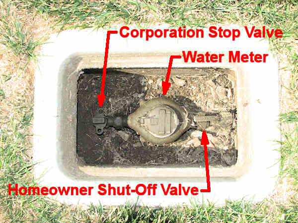
Photo of an underground water service utility box
containing a corporation stop, water meter, & homeowner shut-off valve.
The photo above is of a particularly nice set-up. Not only is there a corporation stop but there is also a homeowner shut-off valve with an easy to use handle. No need to use a special key, the homeowner can turn off the water themselves without tools in an emergency. I cleaned up the inside of this box before taking the photo. A valve box like this will often have ants, spiders and other disgusting stuff in it so be careful when opening them up. I even found a dead turtle in one once!
Sometimes in cold weather areas there is not a corporation stop located outside. The corporation stop is in your house, usually in the basement, crawl space, or a utility room. In this case you’re pretty much screwed, because the water service pipe is likely owned by the water company and even if it isn’t you can’t easily shut off the water to replace it. Before giving up, call your water company directly (use their local customer service number, not 811) and ask if they have a shut-off someplace between their mainline and your house. Maybe you just couldn’t find it. As a last resort, ask them if they will install a new, larger supply pipe for you. Most of the time they will, but they probably will charge you for doing it. Don’t be surprised if they refer you to a plumbing company to actually do the work.
Add a Second Pipe or Replace the Original Pipe?
How you proceed from here depends on the current layout of your water supply, your budget, and future maintenance concerns. Select the method below that best applies to your needs.
The water meter is installed right next to the corporation stop, or you don’t have a water meter.
- You can simply tap into the existing water supply pipe right after the water meter. Then install a brand new larger size pipe to the sprinkler system. The pipe leading to the irrigation system would be the “new” supply line, using the revised GPM from the table above. The existing supply line to the house would remain unchanged, and the existing flow to the house would remain unchanged. Only the sprinkler system would get the increased flow.
- Tap into the existing supply pipe right after the corporation stop/water meter and install a new second pipe to the house parallel to it. About a foot out from the house connect the new pipe back into the old, smaller pipe leading into the house. That way you don’t need to change any of the pipe in the house walls. This creates two supply pipes side-by-side to the house, with the water going through both of them. The advantage is that this saves some money, as the new pipe can be the same size as the old pipe. The water will go through both of the pipes, so the flow will be much greater than previously (but not doubled, other restrictions still exist, such as the gooseneck and corporation stop.) The downside is that you will now have two separate pipes going to the house. That means twice as much pipe that can break or leak someday. Plus the old pipe will still be there and because it is old, it is more likely to leak or break. Because this method creates future problems, it is not recommended by most professionals.
- Remove the existing water supply pipe between the corporation stop/water meter and the house and replace it completely with a new, larger pipe. About a foot out from the house connect the new pipe to the old, smaller pipe leading into the house. That way you don’t need to change any of the pipe in the house walls. This is the most common method used and is generally the best option.
The water meter is installed more than five feet away from the corporation stop (typically inside the house.)
The options for pipe replacement are essentially the same as those above, however in this case you need to replace the pipe between the corporation stop and the meter. Typically in this situation the meter is inside the house. However, if the meter is someplace out in the yard you will also need to replace the pipe between the meter and the house.
It is much easier if you don’t actually replace the short section of pipe that goes into the house through the wall or floor. Reconnect the new pipe to the old, smaller pipe about a foot outside of the house wall. That leaves a short section of the old pipe going into the house, but is a lot easier than replacing the pipe through the wall or floor. The water will squeeze through the short section and it will work fine as long as there isn’t more than 5 feet of old pipe left between the point you connected the new pipe and the water meter. If there is more than 5′ left, you will need to install new pipe through the wall, or replace the old pipe inside the house once it is through the wall. In other words you leave a short section of the old pipe going into the house through the wall. Once inside it is easier to install a new, larger pipe. You will tap in your new sprinkler system as close as possible after the water meter. Unfortunately, you will have to route the new sprinkler supply pipe out through the wall, which means you will have to drill a hole in the wall. Be sure to seal the hole around the pipe with a good quality flexible water-proof caulking compound! The pipe will move as it expands and contracts, so the caulk needs to remain flexible after it has cured. (Do not use cement for sealing the hole! Standard cement, plaster, and concrete mixes are NOT waterproof!)
Other Items to Consider
Plastic pipe must generally be installed at least 18 inches deep, measured from the top of the pipe to the soil level. All pipe should be installed below the frost line. In some areas that might be 4 feet or more deep. Your local building authorities will have specific requirements on how deep the pipe must be.
![]() How do you connect the new pipe to the old? Most professionals use a compression coupling. If you don’t know what that is, ask at a hardware store. If you make a threaded connection between plastic and metal pipe see the How to Connect Plastic Pipe to Metal Pipe FAQ.
How do you connect the new pipe to the old? Most professionals use a compression coupling. If you don’t know what that is, ask at a hardware store. If you make a threaded connection between plastic and metal pipe see the How to Connect Plastic Pipe to Metal Pipe FAQ.
Well, that’s it for this FAQ. Have fun, and remember, safety first when digging and working with trenches. Follow all OSHA requirements. See OSHA’s guide to working around trenches.
Stopping Low Head Drainage Sprinklers that Spit Air
What Is Low Head Drainage?
Water that flows onto the sidewalk or curb after the sprinklers turn off, but then stops after a few minutes, is due to a phenomena called “low head drainage”. This occurs when the sprinkler system is installed on a sloped area. The slope does not need to be very high, a change of elevation of less than a foot will often create low head drainage. After the sprinklers are turned off, the water in the pipes drains out through the lowest sprinkler heads and is replaced with air. The easiest way to tell if you have low head drainage is to watch the sprinklers when you turn them on. If they spit and spew lots of air when the valve is turned on, then you have a low head drainage problem. Obviously the water that drains out of the pipes is wasted. The spewing and spitting of air every time you turn on the sprinklers also puts a lot of stress on the pipe and sprinklers.
Leaking Valve or Low Head Drainage?
If you have water flowing from a sprinkler head continuously, even when the sprinkler system is off, then the problem is a leaking control valve. The primary difference between low head drainage and a leaking valve is that low head drainage results in water flowing from the lowest sprinklers for a while after they run, but the drainage stops after the pipes are fully drained. (It may take several hours for the water to drain out of the pipes.) If a valve is leaking the water will run out of the lowest sprinkler head all the time, 24 hours a day, every day. A typical indication that the problem is a leaking control valve is moss or algae growing on the sidewalk due to the constant flow of water. Another common sign is puddles of water around the lowest sprinklers that never dry out. To fix the leaking valve you must disassemble the valve, clean it, replace any bad parts, then reassemble it. See How to Repair a Irrigation Solenoid Valve for instructions. It is possible and common to have problems with both a leaking valve and low head drainage. Fix the valve first, then check for low head drainage.
How to Stop Low Head Drainage:
To fix low head drainage you need to have special anti-drain check valves installed at the sprinkler heads. These check valves prevent the water from draining out of the pipes through the lowest sprinklers. In most cases these check valves are built into the sprinkler head. The anti-drain check valve is an optional feature available when you purchase the sprinkler. This check-valve option is available on all major brands of sprinklers. The anti-drain check-valve closes and holds the water in the pipes when the sprinkler system is off. These built-in check-valves don’t cause any drop in performance of the sprinklers, so they don’t have any impact on your sprinkler system design. Many major brands of sprinklers can be retrofitted with a new internal check valve, although the retrofit kits are hard to find. Most pros simply buy a new head with the check valve feature and replace the old sprinkler with the new one.
You can also buy separate check valves that can be installed on the pipe under existing sprinkler heads. These are a lot harder to install, you need to dig up the sprinkler head, remove it, install the new check valve on the riser pipe, then screw the old sprinkler back into the new check valve. Then comes the hard part- the length of the check valve you just added makes the sprinkler sit about 3 inches higher than it was before! So now you need to lower the sprinkler head. There is also another catch to the retrofit type check-valves; they do result in a drop in the sprinkler’s performance. They typically create a drop in water pressure at the sprinkler inlet of 2 to 5 PSI. In addition to the performance drop the retrofit devices are often more expensive than simply replacing the sprinkler with a model that has a built-in check valve.
Where do you buy sprinklers with check valves or retrofit check valve? Check valves and sprinklers with built-in check valves are often not available at discount stores or big box hardware stores. You will probably need to get them from a local irrigation specialty store or online.
A tentative change to the language of the State of California’s Water Conservation Laws will make the use of low-drainage check valves mandatory for new sprinkler systems starting in the year 2010, and may also require retrofit of many older sprinkler systems with check valves. Expect other States where water conservation is an issue to also implement this requirement.
Irrigation and Expansive Soils
What is Expansive Soil?
Expansive soils can be found in many areas. Expansive soils expand in size when they get wet, and then shrink as they dry out. As the soil expands and contracts it can create enough force to cause major damage to building foundations, patios, and sidewalks. Expansive soils are also sometimes called shrink-swell soils, swelling soils, adobe, clay, or caliche soils. The damage caused by expansive soil is similar to that of frost heave found in northern regions, but it is NOT the same thing!
Identifying Expansive Soil
Soil that cracks or fractures when it dries is often a sign that it is expansive; however a lack of cracks does not necessarily indicate that the soil is not expansive. Other expansive soils take on a popcorn like appearance when they dry, they look like someone spread little lumps of popcorn shaped dirt on the soil surface. Expansive soils are often clay like, becoming very sticky when wet and hard and brittle when dry. The best way to determine if the soil at a location is expansive is to have an expansion test performed by a soil expert. Expansive soils are common in desert areas, and also in river bottoms or valleys formed by sediment. They typically form in areas that were once covered by seas or lakes. For example, they are commonly found in the deserts of Arizona, the valleys of Colorado, and coastal plains like the Los Angeles Basin and the low lying areas around San Francisco Bay. Often your local government building department can tell you if the soil in your area is known to have expansion problems. Links at the bottom of this page lead to websites with maps of expansive soil areas and more information on expansive soils.
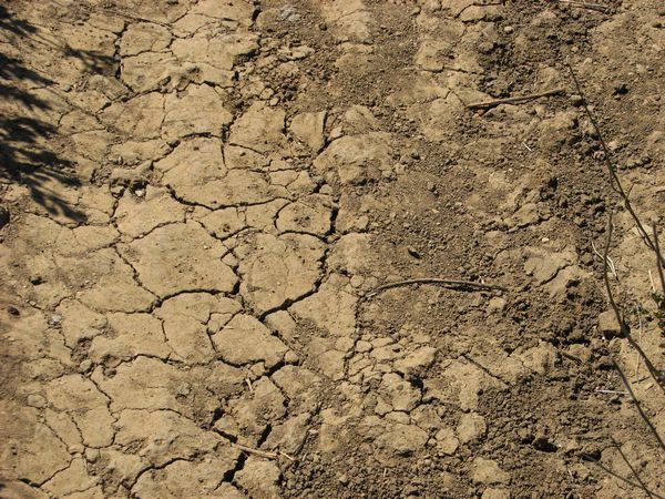
Typical cracking of expansive soil when dry.
Limitations of this Article
Use of this information is at your own risk. Expansive soils vary widely so all I can offer here are broad ideas for ways to deal with it. You will need to decide for yourself the appropriateness of these ideas to your situation. If your soil is extremely expansive you should have a Soils or Geotechnical Engineer advise you on ways to deal with it (they are most often listed under the headings “Engineers – Geotechnical” and/or “Engineers – Soils” in your local phone directory.) Because of the extreme and costly damage that can result from soil expansion, you need to use extreme care in how you deal with it. Please see the Terms of Use for this website.
Water and Expansive Soils
Expansive soils either expand or contract as the amount of water or moisture in them changes. It doesn’t matter if the water is from rainfall or irrigation; the damage is the same either way. In a very simplified explanation, the soil pulls water into it, where the water is stored between the tiny soil particles. Since the water takes up space between the soil particles, the area occupied by the soil expands. The key to controlling damage is to keep the moisture level in the soil next to and under foundations, sidewalks or patios at a uniform level of moisture at all times. If the soil is dry, you want to keep it dry, if it is slightly wet, you want to keep it slightly wet. The amount of moisture in the soil isn’t nearly as important as avoiding changes in the moisture content of the soil.
Concrete Materials
When expansive soils are present it is important to use reinforced concrete to resist the soil movement. This is important because no matter how careful you are, there will be at least some minor soil expansion, and you must be prepared for it. Building and wall foundations should be designed by a qualified engineer. This is not a place to cut corners! Seek out qualified help for the design of foundations. Repair of building damage caused by soil movement can be horrifyingly expensive!
All concrete, including sidewalks and patios, should contain steel reinforcement materials such as rebar and steel mesh. Placing steel in the concrete strengthens it and reduces concrete heaving and cracking. Concrete patios should also have thickened edges with rebar in them to resist soil movement. A local licensed architect, landscape architect, engineer, or concrete contractor can advise you on the necessary thickness of the reinforced edge and the type and quantity of steel mesh and rebar to use. Be sure to discuss with them your budget, and how much cracking and heaving you are willing to accept. Often a compromise is required between cost and having a perfect concrete surface.
The use of concrete pavers or bricks is another option for patios and sidewalks in areas with expansive soils. The pavers are installed without mortar. As the soil expands and contracts the pavers simply move with the soil. The disadvantage of this is that the surface may become very uneven as the pavers move and shift. The advantage is that the pavers generally don’t crack like concrete. Another advantage is that if the pavers become uneven you can remove and reinstall them. Removing and reinstalling them is a lot of work, of course!
Controlling Soil Expansion
The most obvious way to keep expansive soils from expanding is to keep water off of them. Rainwater from roofs should be collected in gutters and then piped away from the building. Drainage should direct water away from buildings. The soil should slope away from buildings for at least 5 feet out from the wall, further is better. While this has nothing to do with irrigation, I mention it because it is important to keep all water away from the building, not just irrigation water. Also keep trees and large shrubs at least 10 feet from buildings as the roots can remove moisture from the soil next to the building and cause it to shrink and collapse.
One way that expansion of soils is controlled by architects and engineers is by mixing lime or other anti-expansion products into the soil. Irrigation water will leach lime and other materials out of the soil, which defeats the purpose of the treatment. Be sure to check to see if the soil under your foundation was treated with lime or a similar anti-expansion material prior to building the structure. If the soil was treated, you need to keep irrigation water away from the treated areas if possible. If possible consult with the building designer as to how far away you need to keep the irrigation from the treated area. If you can’t get a recommendation, keep the irrigation at least 5 feet away. Aprons around the building, as described further below, are a good solution when the soil has been treated.
Another way that engineers deal with expansive soil is to remove the soil and then reinstall it in severely compacted layers (usually with lime added), or just totally replace it with non-expansive soil hauled in from someplace else. This is fairly common in residential building. Normally the soil within 3 to 5 feet of the building foundation will be replaced to a depth of 4 or 5 feet. Be careful not to mix soil from elsewhere around the site with this soil. Also be careful not to mix soil amendments into this area as they will change the non-expansive soil properties. It is best to simply not plant anything within 5 feet of the building foundation. Remember that even if the soil around the building has been replaced or treated, you will still have to deal with expansive soil problems under your driveways, sidewalks and patios.
Finally, architects and engineers may seek to control soil expansion by use of irrigation to help maintain a constant moisture level in the soil. This is a bit tricky because if the irrigation ever fails for any reason, expansion or contraction will occur. This method also requires almost pinpoint accuracy in scheduling irrigation. In the real world this is pretty much impossible to achieve.
Most often some type of compromise solution utilizing several of the above methods of controlling soil expansion is used. In these compromise solutions all water (both from irrigation and rainfall) is kept out of a “no-water zone” that extends at least 3 feet away from the foundation, and often 5 feet. Typically an impermeable apron of some sort is used for this. Then irrigation is used at the edge of this “no-water zone” to maintain a reasonably constant moisture level surrounding it. The following paragraphs look at methods of keeping the “no-water zone” dry and irrigating the edge of the “no-water zone”.
Concrete Aprons
Probably the best method of keeping water away from the building foundations is to use an impermeable apron around the building to keep water away from the foundation. One way this is done is to pour a concrete “apron” all the way around the foundation. The apron needs to extend between 3-5 feet out from the foundation. A plastic moisture barrier sheet is placed under the concrete, because concrete is not water-proof and moisture will seep through it. Also water will flow through the concrete at cracks and expansion joints. It is important that the surface of the concrete apron is sloped so water drains out away from the building and does not pool on the concrete surface. When using a concrete apron you need to understand that the expanding soil will break the concrete apron, and cause it too heave. The only purpose for this concrete is to keep water away from the foundation; it is not intended for use as a sidewalk or patio. It is accepted that soil expansion and contraction due to water seeping under the concrete will result in the concrete becoming uneven and broken! If you want plants up next to the building, put plants in containers on top of the apron. If you want to reduce damage to the concrete apron, add a moisture barrier at the outer edge of it as described below.
Plastic/Rubber Aprons
Another way to keep the perimeter areas dry is to use a plastic or rubber barrier and then cover it with rocks, gravel, bark, or some other loose material. This is often visually more pleasing than the concrete apron above, as the loose material covering the apron does not develop ugly cracks, like concrete. The downside to plastic is that it is not as permanent, yearly checks are needed to make sure the plastic does not have tears or holes in it, and the plastic must be periodically replaced as it will wear out over time. Rubber is more durable but also breaks down over time. The thickest plastic/rubber that can be afforded should be used, thicker material will hold up longer. 20mil thick plastic/rubber is often the minimum thickness used. This plastic/rubber material is often sold for use as pond liners. The plastic/rubber apron must be glued at the top to the edge of the foundation so that water will not enter between the barrier and the foundation. Use high-quality glue or double-stick tape that remains flexible when dry. All joints in the plastic/rubber should be overlapped by at least 8 inches and glued or taped together. The plastic/rubber should not be exposed to any sunlight, as sunlight will make it wear out much faster. Cover the plastic/rubber completely with something to keep sunlight off of it. Generally the covering material is at least 3 inches deep over the plastic/rubber. If you cover the barrier with dirt it is likely weeds will grow and create holes in it, so dirt or soil is not a good choice. It is very important to not let weeds grow on top of the plastic/rubber. If you put potted plants on top of the apron area, check often to make sure roots are not growing out of the pots and down into the barrier!
Typical Apron Detail, click on detail to print.
Moisture Barriers
Moisture barriers are most often used to reduce expansion damage to less important structures like hardscape. (Paved landscape features like driveways, sidewalks, and patios are called hardscape. Hardscape can be made from many materials, such as concrete, bricks, flagstone, etc.) Moisture barriers are also used in areas where the soil is only minimally expansive. A moisture barrier keeps water from seeping sideways under the adjacent hardscape, but does not keep water away from the edges of the hardscape. This reduces lifting of the hardscape surface by the expansive soil. It does not prevent the adjacent soil from moving the hardscape sideways, which is why it is not suitable for areas with highly expandable soil. A moisture barrier is a sheet of thick plastic or metal set vertically along the edge of the hardscape. The moisture barrier typically extends at least 24 inches in depth; often 36″ deep barriers are used. The moisture barrier must be glued at the top to the edge of the hardscape so that water will not enter between the barrier and the hardscape. Use high-quality glue or double-stick tape that remains flexible when dry. Moisture barriers should be checked at least once a year to assure the barrier is still firmly glued to the edge of the hardscape. Moisture barriers need to be continuous with no gaps, cracks, or unglued joints between the sections. Typically the moisture barrier sections are both overlapped and glued or taped together at any joints. It is critical that water not be able to get through or behind the barrier. The moisture barrier needs to be thick enough that roots will not easily grow through it and create holes in it. Often 20mil and thicker plastic is used. If metal is used for the moisture barrier it should not be something that will rust.
Typical Moisture Barrier Detail, click on detail to print.
Using Irrigation to Maintain Uniform Moisture
Often Geotechnical Engineers will recommend that irrigation be used to maintain “uniform soil moisture” levels. The theory is that if the moisture level stays uniform at all times, the soil will neither expand nor contract. This is easier to say than it is to do. While irrigation can maintain the needed water in the soil, it takes a top quality irrigation system to apply the water uniformly and it takes skill in timing the irrigations to keep the amount of water in the soil constant and uniform. If the irrigation system is not maintained and operated very carefully, it can worsen the problem rather than help. Remember that the key is keeping the soil moisture at a constant, uniform level. If you decide to keep the soil stable by keeping it moist, you must always keep it at exactly the same level of moistness. If it is ever allowed to dry out or become over-saturated it may cause damage. Because using irrigation to maintain uniform soil moisture is difficult, it is best to use irrigation only in combination with the use of a apron or moisture barrier as described below.
Maintaining Water Uniformity in the Soil
Water content of irrigated soil varies tremendously. Immediately after irrigation the water content is very high, and then it recedes with time until the next irrigation. This is true of both sprinklers and drip systems, but sprinklers add even greater variability than drip. As the water moves down through the soil and away from the heat of the sun and air circulation, it disperses. As a result the moisture level in the soil tends to stabilize and become relatively uniform. Stable and uniform soil moisture is exactly what is desired for reducing the soil expansion problems. This is the reason that foundations of buildings on expansive soil are often 3 or 4 feet deep, extending down to where the soil moisture levels are more stable. But often a 3-4 foot deep foundation is not practical, or for whatever reason was not utilized. Fortunately, water also moves sideways through the soil, not just down. So we can mimic this “soil depth effect” at the surface to some degree by sealing the surface so that water neither enters it nor evaporates from it. This way the water can move sideways out from our irrigation source, and as with moving down, the moisture level will become more stable and uniform as we move away from the water source. All we need to do is block water from entering or leaving the soil at the surface level. This is the theory behind the use of concrete and plastic aprons described above. An apron 3 to 5 feet wide is placed around the entire building. Irrigation is installed at the outer edge of this apron. This keeps the irrigation well away from the foundation and helps maintain moisture levels more uniform near and under the building or patio. When water from rainfall or irrigation enters the soil, it moves sideways through the soil, by capillary action, under the edge of the apron. By the time it has moved 3-5 feet sideways under the apron, the moisture level is dispersed and reasonably stable and constant.
It is critical that the irrigation system be run at regular intervals to keep the moisture level stable. I strongly suggest the irrigation be automated with a timer and checked regularly. You can also use automatic soil moisture sensors to control the irrigation. There are many available on the market, but my experience has been that they are not fool-proof. You can’t just set them and forget them. The oldest type is called Tensiometers. There are also solid state sensors that require less maintenance than the older style Tensiometers. There are constant arguments in the industry as to which is better; I really don’t have an opinion on this. They are heavily influenced by local conditions, particularly soil type and salt content; you will need to do some research to find the one best for your situation. Many of the soil moisture sensors are designed to keep the moisture from dropping below a given level, but do not guard against too much water in the soil.
Drip Irrigation
It is my opinion that you will get the most uniform moisture applications from a drip system. It is important that the drip system uses evenly spaced emitters, generally around 12 inches apart on the tube. There are a number of products that come with emitters pre-installed on a tube at regular intervals. Or you can buy the emitters and tube separate and install them on the tube yourself at uniform spaces. The drip tubes should not be buried unless you use one of the types that use chemicals to prevent root intrusion into the emitters. The only two I know of are Techline (with Techfilter) by Netafim, and DL-2000 by Toro. The drip tube is typically installed 12″ from the edge of the apron. See the Drip Irrigation Design Guidelines for more help with a drip system design. Remember, uniformity of water application is critical to control expansive soils so proper design is very important.
Soaker Hose
Soaker hoses tend to not give very uniform distribution of moisture, and they have a rather limited life span. They may be appropriate for a short term temporary solution prior to installing a more permanent irrigation system. I wouldn’t consider a soaker hose for a permanent solution. If you do use them, the design and operation is similar to drip systems.
Sprinkler Irrigation
Sprinklers may also be used for irrigation around the apron; however the sprinkler spacing must be head-to-head at the edge where the water application needs to be as uniform as possible. Head-to-head means that one sprinkler sprays all the way to the next. So if the sprinkler radius is 12 feet, they should be placed no more than 12 feet apart. The sprinkler heads should be placed at least 6″ away from the edge of the apron. See the Sprinkler Irrigation Design Tutorial for information on designing a high quality irrigation system. Remember, uniformity of water application is critical to control expansive soils so proper design is very important.
Additional Resources on the Web
Here are some good resources for additional study:
Colorado State University Extension- Horticulture Article on expansive soils by C.R. Wilson, J.G. Davis and N. Mejia for Colorado State University Extension- Horticulture.
Missouri University of Science and Technology A very good article on expansive soils with case studies and solutions for foundations and swimming pools. A must-read article if you plan to build a swi
Irrigation and Wind
Wind can really mess up an irrigation system. Even a gentle breeze will blow around the water droplets from most sprinklers. Realistically, a slight breeze from time to time is not usually a problem. But if you expect a steady breeze on a consistent basis, you should take precautions in your irrigation system design. This FAQ will guide you through the possible solutions to wind problems.
If Possible, Avoid Using Sprinklers:
The best way to deal with wind when designing an irrigation system is to avoid using sprinklers. Anytime you spray water into the air there’s going to be problems with the wind blowing the water around. This is simply unavoidable. So the best approach is to avoid irrigation systems that spray water into the air. A drip system is ideal, as the water is dripped directly into the soil from the emitters. Subsurface (underground) drip systems will work for most lawns, however subsurface irrigation is not for everyone. It is generally more expensive than sprinklers and requires different maintenance procedures.
Bubblers are also a good solution, as the water is also applied directly at the soil level. Bubblers work by flooding small areas of the ground with water. Bubblers do not work well for lawn areas, however. The difference between bubblers and drip is in how quickly the water is applied. With a bubbler the water is applied faster than the soil can absorb it, so it spreads out and floods the area. Bubblers are great for shrubs planted in groups on flat soil where the water can spread out. They are not good for slopes where the water will flow downhill and away. Drip systems emit water very slowly and the water soaks directly into the soil without flooding. With a drip system only an area about 3 feet (1m) in diameter around each emitter (or dripper) becomes wet (the size of the area varies with soil type and how much water is applied.) So at least one emitter is required for each plant, for larger plants you might need several emitters. Drip systems work well on slopes. See the Drip Irrigation Design Guidelines for more information.
Re-Design Your Landscape:
Another way to deal with wind problems is through the design of your landscape. In windy areas it is common to design landscapes so that there is no lawn directly adjacent to sidewalks, driveways, roads, buildings, or anything else you don’t want to get wet. A typical lawn for a windy area would be designed to look somewhat like a golf green surrounded by shrubs. (Use a rounded shape for the lawn, like a jelly bean or the meandering edge of a mountain meadow surrounded by forest.) The lawn is then irrigated with sprinklers, and the shrubs are irrigated with bubblers or drip irrigation. The sprinklers are adjusted so that the ones on the upwind side spray slightly backwards into the wind, so that the wind blows the water back onto the lawn. In other words a sprinkler that would normally use a half-circle nozzle on the upwind side might utilize a two-thirds circle nozzle so that it sprays back into the wind slightly. On the downwind side the sprinklers are adjusted just the opposite, with the knowledge that water will be blown slightly down wind. So on the downwind side a sprinkler that would normally have a half-circle nozzle might now use a one-third circle nozzle. Because the lawn is surrounded by shrub areas, any water that blows outside of the lawn area will not be wasted.
Sprinklers and Wind:
The remainder of this article will deal with sprinkler systems and the unique challenges that wind presents when designing a sprinkler system.
Don’t Water When the Wind Is Blowing:
I guess it is obvious, but it is an important factor so here it is: the best way to avoid wind problems is to avoid the wind altogether. Even in the windiest locations there are often times of the day when the wind doesn’t blow as much or as strong. This is typically in the early morning hours. Try to design your sprinkler system so that you can irrigate during these reasonably wind-free hours of the day. This may require you to obtain a larger water source, so that you can irrigate more area in less time. Do a little research to see what time of the day the wind blows the least. In many windy areas the wind dies down a few hours after sunset and doesn’t start up again until shortly after sunrise. Use a fully automatic irrigation system and design it so that it can operate during these reasonably wind-free hours of the day.
Will watering at night cause any harm? Watering at night and during early the morning saves water, as there is less evaporation at these times of day. In humid climates watering at night can lead to mold and mildew problems, however this is not typically a problem in windy areas, as the wind tends to quickly dry out the residual moisture on the leaves. A well-established lawn should not need to be watered more than once a day, even in hot, windy areas. Shrubs need watering even less often. So watering at night, rather than during the day, should not be a problem. In hot, windy areas lawns and other plantings will often look wilted by late afternoon, this is often hard to avoid. Watering during the heat of the day typically does not provide much help with this as the problem isn’t a lack of water in the ground. The problem is that the plant simply can’t pump enough water through it’s roots to stay crisp and fresh looking. A healthier plant with more and better roots is the solution to this problem, and watering too frequently can actually cause less roots to grow. During the establishment period for new plantings (typically the first 90 days) it is necessary to water more frequently, a new lawn often needs water every 2-3 hours on a hot afternoon. When establishing a new lawn it is often necessary to hand water some areas when the wind is blowing in order to assure they get enough water.
Sprinkler Head Selection:
Wind impacts sprinklers when it blows the water away from the place where you wanted the water to be applied. This is called wind drift. Two factors have a large effect on the amount of wind drift. The first is the size of the water droplets the second is the size of the water stream.
Spray-type sprinkler heads: Mist and small water droplets are easily blown by the wind. So it is best to avoid sprinklers that create a lot of mist or very small water droplets. Spray-type heads tend to create lots of mist, especially if there is excessive water pressure at the sprinkler head. This can be addressed simply by properly adjusting the sprinkler to minimize the amount of mist created and not over-spacing the sprinklers. A small screw on the top of most spray head nozzles allows them to be adjusted so that there is a minimal amount of mist created. To avoid over-spacing, if the sprinkler company’s literature says the sprinkler has a 15 foot (4,5m) radius, then do not space them more than 15 feet apart! Remember that for the most efficient operation, most sprinklers require 100% overlap of the area watered by each sprinkler. Yes, I know that seems like a lot of sprinklers, but it is the way it works, so get used to it. Each sprinkler needs to throw water all the way to the next sprinkler. Low angle sprinklers are generally less affected by wind, however you need to use a sprinkler with at least a 4″ pop-up height so that the low-angle spray does not hit the grass.
Rotor type sprinkler heads: Like the spray-type heads they must be spaced so that there is 100% overlap of the watered areas. When using rotor-type sprinklers avoid models that use less than 3 gallons per minute (11.4 l/min) flow. The higher flow rates of larger nozzles result in larger water droplets that are not blown around as easily. Rotors that have multiple streams of water are called stream rotors. Stream rotors can be identified by their appearance when operating, the streams of water look like spider legs rotating around the sprinkler. Stream rotors tend to have very small water streams that are easily moved by the wind. It is probably best to avoid them if you must irrigate when the wind is blowing. The closer the water is to the ground the less likely it is to be blown by wind. So try to avoid sprinklers that have high trajectories. Low angle sprinklers are less affected by wind. The farther the water has to travel through the air, the more likely it is to be blown off-course by wind. Thus in windy areas it is best to use shorter radius sprinklers.
My preference is to base the selection of either rotors or spray-type sprinklers on the size and shape of the area. I generally use rotors in areas where all the dimensions are more than 20 feet (6m). In narrower areas I use spray-type heads. Both sprays and rotors have issues with wind and in my opinion neither provides a clear advantage in windy areas. When dealing with wind, I have found that the type of sprinkler isn’t nearly as critical as proper spacing and adjustment.
For more on sprinkler head spacing see the Sprinkler Spacing Page of the Sprinkler Irrigation System Design Tutorial for the correct method of designing a sprinkler system. Wind makes it critical that you design the system properly; the wind leaves you with no room for error in your sprinkler spacing or pipe sizes.
Valve Zones for Windy Locations:
Design your irrigation system so that the perimeter edges on the up-wind and down-wind sides are controlled by separate valves. Wind problems tend to be the worst along the up-wind edge of the irrigated area. In this area the wind blows the water away from the edge, leaving it dry. The next worst area for wind problems is on the downwind edge, where the wind tends to blow the water out of the irrigated area. Put the sprinklers on both these edges on their own separate valve circuits if possible. This allows you to run those valves during more reliably wind-free times of the day. It also allows you to increase or decrease the watering time in those areas to compensate for the wind problems. If cost or another factor makes it difficult to separate both edges, then try to separate only the up-wind edge to the extent possible. It’s OK to fudge a little and include a few heads that aren’t on the edge on the same valve circuit with the ones on the edge.
Tighten Spacing On the Upwind Edge:
As previously mentioned, wind problems tend to be bad on the upwind edge of the irrigated area. One means of dealing with this is to place the sprinklers closer together on the upwind edge. There is no room for sprinkler spacing errors on the upwind edge. If you’re using spray type sprinklers I suggest a maximum distance between sprinklers of 12 feet. Spray type heads used at 12 foot spacings have water droplets that are considerably larger and less susceptible being blown by the wind. If you are using rotor type sprinklers try to keep the spacing slightly closer than head to head. That means the water from one rotor should spray all away to the next rotor along the upwind edge. Don’t stretch the spacing at all. When in doubt, reduce the space between heads and add another sprinkler head. On the upwind edge it is always better to have more heads than to have less.
Wind Detectors:
To avoid irrigating during times when the wind is blowing you can use a control system that detects wind. One method of doing this is to install a wind speed monitor nearby. It detects high wind speeds and shuts off the irrigation. It does this in a non-smart way; it just shuts off the power to the valves and irrigation stops. This is a really effective method but there is a drawback- the irrigation gets skipped and the landscape may dry up if the wind blows for several days! So if you use a wind detector like this you need to keep an eye on it, wind can make the landscape dry out fast. Some high-end irrigation controllers are smart enough to know that the irrigation was shut down and will attempt to reschedule it at a wind free time. Finally, some irrigation controllers have a remote programming feature where the irrigation schedule is calculated and controlled by a company for you on a subscription basis. In this case the company determines that the wind is blowing in your area based on a wind detector, a nearby weather station, or the weather forecast. When the wind blows hard enough to be a problem they shut off the irrigation and reschedule it for you.
That’s it. These tricks and techniques should help you to have a better irrigation system in windy areas. Remember, the best trick is to avoid the wind by irrigating when it isn’t blowing!
Irrigation Master Valves
A master valve is an automatic valve, typically an electric solenoid type valve, that is installed at the point where the irrigation system connects to the water supply. The master valve is wired to a special “master valve circuit” on the irrigation controller. (Sometimes this circuit is called a “pump start circuit”. Both types of circuits work similar or identical, and can be used for a pump and/or a master valve.) The irrigation controller turns the master valve on and off. Most, but not all, irrigation controllers have a master valve circuit built in to them.
How a master valve works:
Zone valves are the individual valves that operate a group of sprinklers or drip emitters. A typical irrigation system has several zone valves. Typically one zone valve is turned on at a time, and controls the irrigation in a specific area of the yard. Whenever one of the irrigation zone valves is told to open by the controller, the controller also signals the master valve to open. So the master valve is a little like a back up valve, or a fail-safe valve. The purpose of the master valve is to shut off the water to the irrigation system when none of the zone valves are operating.
Benefits of master valves:
- If a zone valve develops a leak, or doesn’t close, the master valve will act as a back-up to shut off the water. Note that the water will still be on as long as any other zone valves are on. But when all are finished watering, the master valve will shut off the main water supply to the entire irrigation system. While this does not eliminate the water loss or damage, it may minimize it.
- If the mainline pipe (the pipe from the water source to the zone valves) breaks, the water will be turned off at the end of the irrigation cycle and this may minimize water loss and damage. This is especially useful if the mainline is on a hillside, where a leak might cause massive erosion and property damage. Again, the water will still be on as long as any other zone valves are on, so it only will stop the flow when the entire irrigation system is off.
- Some of the more expensive irrigation controllers can use a flow sensor in combination with a master valve to detect leaks and shut off the entire irrigation system. The controller memorizes how much water is used by each valve zone. If the flow sensor shows that the water use is higher than expected, indicating a leak, the controller detects the change in flow and closes the master valve. Unfortunately, most commercial landscape maintenance companies I have dealt with do not know how to use one of these sensor systems, and they disable the sensor. This has happened about 90% of the time on projects I have used these systems on.
Disadvantages of master valves:
- Leaks are more likely to go unnoticed and not get repaired when a master valve is used. This is because most irrigation systems run at night, when nobody is around to see the leak. During the day, when the irrigation system is shut down by the master valve, the leak is not noticed and goes unreported. My experience is that most property owners, homeowners and, yes, even professional landscape maintenance providers, do not regularly check the irrigation systems for proper operation. They make repairs only when damage becomes extreme or someone complains. No, this is not how it should be done, but sadly it is what I see 90% of the time. For this reason a master valve can actually increase the amount of water wasted when a leak develops.
- Master valves lead to premature failure of both PVC and PE (poly) mainlines. This is due to the stretching and contracting of the pipe each time the system is pressurized and then depressurized. This problem is greatly exaggerated at higher water pressures (over 65 PSI or 4,5 bars).
- A master valve can increase the severity of water hammer if the mainline has a pinhole, or one of the zone valves has a slight leak, or if the zone valves close slower than the master valve. This is due to the water draining out of the mainline. When the master valve opens and the pipe refills, the water charges through the empty pipe at a very high velocity, slamming into the tees and ells and causing damage to the pipe system.
- A master valve is one more item that can fail and require maintenance, plus it adds to the initial cost of the irrigation system.
What type of valve should be used for a master valve?
Any electric solenoid valve can be used as a master valve, except for anti-siphon valves. Anti-siphon valves may not be used as master valves. (You should never install an anti-siphon valve in a location where there is another valve downstream of it, if you do it will break the anti-siphon part of the valve.) Many professionals like to use brass valves for master valves due to the higher pressure rating and a general attitude that “if it’s brass it must be better”. I don’t feel that a brass valve is necessary unless you can’t find a plastic valve with a high enough pressure rating. Note that the pressure rating of the valve should be at least double the expected water pressure in the irrigation system. So if you have 75 PSI, or 5,2 bars, of water pressure the valve should be rated for at least 150 PSI, or 10,4 bars. If the master valve is installed before the irrigation system filter, then a “contamination-proof”, “self-filtering”, or “dirty water” valve would be the best type of valve to use as the master valve. These are expensive valves that have a small built-in filter to help protect the valve from dirt, which is a major cause of valve failure. If a valve with a filter is too expensive, a valve featuring a “self-cleaning metering rod” or “self-flushing ports” would be the next best thing. At a minimum the master valve should be equal in quality to the zone control valves. I typically install a filter upstream of the master valve, so most of the time I use the same valve model for the master valve as I use for the zone control valves. If you are designing an irrigation system that uses hydraulically operated zone valves, you will want to use a hydraulic operated master valve rather than an electric solenoid type. Hydraulic operated systems are rare, so if you don’t know what I’m talking about it doesn’t apply to you!
Where to install the master valve:
The master valve can be installed anywhere you would like. It can be before or after the backflow preventer and or the pressure regulator (if used). A few water districts do not allow any valves to be installed before the backflow preventer, but most don’t care. I typically place them in an underground box after the backflow preventer and the pressure regulator. In most cases, putting it after the pressure regulator allows the use of a less expensive valve with a lower pressure rating. In freezing climates the basement, utility room, or a heated shed is a good place for them. If you need to repair the master valve it will spill water when you open it, so make sure it is not installed in a location where a little water spilling out will cause harm. Some master valves spit water out of the valve when they are manually turned on. I suggest that the master valve not be used as the emergency shut off/winterization valve for the irrigation system. Use a separate ball valve installed before the master valve for that. Like all electric valves, sooner or later it will need to be repaired, and you will need to shut off the water while you fix it.
My opinion; when should you use a master valve?
If your mainline is located in a place where a leak might cause severe property damage or a danger to the public, you should use a master valve. If you are willing to pay the price of a flow monitoring irrigation controller with a flow sensor, a master valve can be used as a water conservation measure. The controller should be programmed to shut the master valve only if a leak is detected, and not at the end of every irrigation cycle. For a typical residential irrigation system, and even many commercial systems, I don’t think the benefits of a master valve outweigh the risks or justify the cost. Many water districts in areas with limited water supplies require the use of master valves as a water conservation measure. I absolutely oppose the use of master valves as a water conservation measure when not used with a flow sensor and appropriate irrigation controller. My experience indicates they actually result in an increase in wasted water!
Increasing Minimum Available GPM
Help, I Need More Water!
How can I get more water out of my existing water supply pipe? How can I increase the minimum available GPM for use in my irrigation design? These questions and variations of them are among the most frequently-asked questions I hear. A typical question would be something like this: “I have a 5/8″ meter and a 3/4″ copper supply, so according to the Sprinkler System Design Tutorial I only have 10 GPM available. This doesn’t seem like very much, so I did a bucket test and got 18 GPM from it! So why can’t I use the 18 GPM figure from my bucket test for my Initial Design Flow?” Well, the answer is you can use that higher value. Of course, you can also jump off a cliff if you want to, but it isn’t a wise choice. There is more involved in determining your Design Flow than just measuring water in a bucket. The good news is that you MAY be able to use a higher flow. The bad news is it isn’t easy or fast to determine if you can! So be patient, and read on. I know this is a long tutorial, but there are a lot of variables and I want to try to give you enough information to make a good decision.
The rest of this FAQ assumes your water is coming to you from a water supplier. If you pump your own water from a well, stream, or pond the only way to increase your water flow is to install a newer and/or larger pump, larger pipe leading to and from it, and possibly drill a deeper well. You will need to see the Irrigation Pumping Systems Tutorial for details on how to do that.
GPM definition: GPM is the standard unit of flow used in the USA, it means “gallons per minute”. This tutorial uses GPM as the flow measurement. Metric countries use liters per minute (l/m) to measure flow. Multiply GPM x 3.78 to get liters per minute.
There are obvious advantages to having a higher flow rate available for your sprinkler system. Increasing your available water supply will reduce the number of valves you need, which could result in a less expensive controller, less wire, and, in general, a lower cost. The best way to increase the amount of water you have available is to have the water supplier install a larger pipe to your property. But in most cases these good options are expensive or not even possible. So the next best solution is to try to force more water through the existing pipe. Unfortunately, there is a lot of really bad advice floating around on how to determine the maximum flow for your sprinkler system. Most sprinkler contractors and sprinkler design guides focus on keeping the short-term costs down. After all, they want to make a sale, and the best way to do that is to have the lowest price. They will save you a few bucks up front when buying your system at the expense of hundreds or even thousands of dollars in repairs later on. The theory is that you are happy you saved money today– and they won’t be around when you are unhappy later! I don’t play that game, so we’re going to look at the risks, and then you can decide if it is worth it.
The Problems with Higher Flows
First, this FAQ assumes you have already worked through the process of calculating your flow used in my Sprinkler System Design Tutorial, and that you want to use a higher flow than what was recommended there. If you haven’t read through at least the first 3 pages of that Tutorial, I recommend you do it before continuing here. The tutorial describes the best way to determine how much flow you will have to work with in designing your sprinkler system.
Keep in mind that what we are discussing here is the maximum available GPM flow. The maximum available flow is the starting point for your design. The actual GPM you should use for your irrigation system may be lower than this value for any number of reasons. As you work through the tutorial above, you will be able to determine the actual GPM you should use.
Now let’s take a look at the significant risks involved in using a higher flow, so you know what you are getting into. The Maximum Available GPM figures I recommend in the Sprinkler System Design Tutorial are set at the maximum safe flow for your pipe size and type, as recommended by the vast majority of experts and the pipe manufacturers. It is correct that you can get a lot more water through that pipe. No doubt about it. You can force an almost unlimited amount of water through a pipe if you put enough pressure on the water. But is that wise?
Scrubbing
Velocity is the measurement of the speed at which the water is moving through a pipe. In the USA irrigation industry we measure this speed in feet per second (abbreviated feet/second or ft/sec). Flowing water is a funny thing, it seems rather harmless, but at very high velocities bad things begin to occur inside pipes. The first is what is called “scrubbing”. Scrubbing is essentially the wearing away of the inside of the pipe one molecule at a time. It results from a number of different factors, but it’s easiest just to picture the water as being very slightly abrasive. It just scrubs away at the pipe. As the water moves faster and faster, this effect gets considerably worse. Therefore, most industry sources recommend that you limit flow velocities to less than 7 feet/second, if possible. If the pipe is larger than 2″, the recommended maximum velocity drops to 5 feet/second. Scrubbing is also worse in metal pipes, the slicker surface of plastics reduces the problem. Scrubbing combined with corrosion is the primary reason that copper pipes in houses develop pin holes over time and need to be replaced.
Water Hammer
The second problem that occurs at high velocities is “water hammer”. Remember the Jan & Dean song Dead Man’s Curve? Let’s say you have a really fast Model A hot rod (what a thrill, can I hitch a ride?) You decide to take it out for a ride on Sunset Blvd. It would be safe to drive at 35 MPH, stupid at 50 MPH and sure death when you hit Dead Man’s Curve at 80 MPH! In the same way, the water in your pipes can go pretty fast, but what happens when it hits that curve? How about if it hits a wall? The answer is called “water hammer”.
Water hammer is caused when a valve quickly closes on the fast-flowing water in the pipe. For a great mental image of this, picture a large, very heavy, very long truck full of bananas driving straight into the face of a cliff. Got the image? Bananas everywhere! One last thing to be aware of is that water hammer problems are much more likely if you have water pressure over 60 PSI. If you want to read more on water hammer I have written an entire tutorial on the topic. You can read it here: www.irrigationtutorials.com/waterhammer.htm.
So can you use a higher flow? Sure, you can. But all bets are off. I know it saves a lot of money if you can use a higher flow and have a few less valves. But if you get a good case of water hammer, you can bet you are going to regret it. When a sprinkler valve shuts off at 4 AM in the morning and it sounds like the house was just hit by a truck, your spouse may hit you! Or maybe you’ll just ignore the noise until the morning one of the hoses under a sink blows off due to the pressure surge, and the house is flooded. Then you may just wish you had spent a little more money on your sprinkler system! Scrubbing, on the other hand, is pretty easy to predict. If you exceed the recommended flows in the tutorial, you are going to get scrubbing damage, especially if you have copper pipe. What is next to impossible to predict is how much damage will be caused. As you increase the flow, the scrubbing gets progressively worse. It also depends on the type of pipe you have and how well it was assembled back when they built your house. If, in general, you have noted that your house is poorly constructed, you might want to think long and hard about this! But if the scrubbing isn’t major, and the pipe and workmanship are good quality, it takes years and years for it to become a problem. How many years varies widely, but more than 10 years seems to be a reasonable expectation.
Well, at this point you need to decide how much risk you want to assume to save a few dollars. Unfortunately, I can’t help you with this. It has to be your decision. So below I’ll give you some new maximum flow rates, and also explain how to do a water hammer test.
Ready to Proceed?
OK, you understand the risks and you want to proceed anyway. The Maximum Design Flows that I give in the Sprinkler System Design Tutorial are based on maintaining a flow below 7 feet/second. Some people in the industry say you can go up to 10 feet per second, especially with smaller pipe sizes. I have never heard anyone with any training recommend a flow higher than that. The maximum flow values in the table below are based on 10 feet/second velocity. Flows over this value pretty much guarantee you will see major damage in the pipe.
Remember that the maximum flow must be based on the most restrictive pipe that the water passes through on the way to your sprinkler system. For example, let’s say your house has a 1″ PVC pipe that brings the water from the water company mainline out in the street to your house. When the pipe reaches the house, it changes to 3/4″ PEX pipe through the house. In this case if you tapped into the 1″ PVC pipe, then the 1″ PVC pipe would determine the maximum flow. This is because the water going to the sprinklers goes directly from the 1″ PVC pipe into the sprinkler system. You wouldn’t need to consider the 3/4″ PEX because the water never passed through it. However, if you tapped into the water supply inside the house after the pipe becomes 3/4″ PEX, then the PEX pipe would determine the maximum flow because the PEX pipe has a lower maximum flow than the PVC. The most restrictive pipe that the water actually passes through determines the maximum flow.
“What if the smallest pipe is really short? Won’t the water just squeeze through without problems? After all, a lot of water squeezes through a valve, and the opening in a valve is pretty small, right?” Yes, that is correct, and you can squeeze the water through. The problem is the scrubbing. A valve is made with a heavy body so it can stand up to the wear, but pipe, particularly copper, is not. My advice is to replace the small pipe section with a larger pipe. But yes, you can squeeze the water through if it is less than 3 feet long and you accept that the pipe will wear out faster.
NEVER EXCEED THESE FLOWS!
(GPM at 10 feet/second)
| pipe type | size | GPM |
|---|---|---|
| copper (type L CTS) | 1/2″ | 7 |
| copper (type L CTS) | 5/8″ | 10 |
| copper (type L CTS) | 3/4″ | 15 |
| copper (type L CTS) | 1″ | 25 |
| steel (galv. IPS) | 1/2″ | 9 |
| steel (galv. IPS) | 3/4″ | 16 |
| steel (galv. IPS) | 1″ | 26 |
| PE “poly” (SDR-7) | 1/2″ | 5 |
| PE “poly” (SDR-7) | 3/4″ | 16 |
| PE “poly” (SDR-7) | 1″ | 26 |
| SCH 40 PVC/CPVC (IPS) | 1/2″ | 9 |
| SCH 40 PVC/CPVC (IPS) | 3/4″ | 16 |
| SCH 40 PVC/CPVC (IPS) | 1″ | 26 |
| PEX (CTS SDR-9) | 3/8″ | 3 |
| PEX (CTS SDR-9) | 1/2″ | 5 |
| PEX (CTS SDR-9) | 3/4″ | 11 |
| PEX (CTS SDR-9) | 1″ | 18 |
| CPVC (CTS SDR-11) | 1/2″ | 5 |
| CPVC (CTS SDR-11) | 3/4″ | 10 |
| CPVC (CTS SDR-11) | 1″ | 20 |
Notes on using the table above:
CTS means “Copper Tube Size”, IPS means “Iron Pipe Size”. SDR means Standard Dimension Ratio (the ratio of the pipe wall thickness in relation to the diameter of the pipe).
If your pipe is larger than 1″, you should have plenty of water, stick with the flows in the tutorial! Larger pipe sizes are much less forgiving of high-velocity flows.
What type of plastic pipe is it? PEX and PE are both polyethylene products. There is a lot of confusion over these two products. True PEX is a stronger form of cross-linked polyethylene that has become popular with plumbers in recent years. Both PEX and PE are flexible, and both have a glossy appearance and slick surface. So how do you tell which one you have? Older PE is almost always black, and in most cases PEX is not black. The surest thing to look for are the letters “PEX” printed on the tubing. Making things even worse, white PEX looks a lot like PVC, especially if it is old or dirty! PEX is easily scratched with a fingernail, PVC scratches, but not easily. PEX was not invented until the ’70s, and it is seldom found in homes built before 1975. (It wasn’t officially sold in the USA until 1985. Of course, if your house has been remodeled, you could still have it in a older house.)
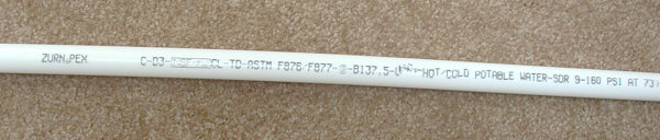
PEX tubing. Don’t confuse it with PE or PVC!
Note the labels “PEX” & “SDR-9”.
PVC plastic pipe is almost always white or gray and is more rigid than either PEX or PE. Another type of PVC called CPVC is sometimes used inside homes and often is found in older mobile homes. It is similar to regular PVC, but will be labeled “CPVC” and most often is a yellowish, gold, or tan color. CPVC in homes is usually copper tube size (look for “SDR-11” printed on the pipe), but is also sometimes IPS (SCH 40). Confused yet? Your best bet is to find lettering on the pipe that says what type it is.
CRITICAL! Your maximum flow MUST be based on the most restrictive pipe size and type between the water company’s mainline and your sprinkler system. Even if you use a 1″ PVC pipe for your irrigation system, if you are tapping into a 3/4″ copper pipe to get the water, then the 3/4″ pipe determines the maximum flow. Think of it this way- you may have a huge mouth, but if you are trying to suck soda through one of those tiny straws used to stir coffee you will not get much soda! The pipes leading to your irrigation system are like that tiny straw. The smallest, most restrictive one determines how much water gets through.
Water Hammer Test:
If you’re going to try using a higher flow, you need to perform a water hammer test. I know this takes time and effort, but it is necessary.
This test is absolutely critical if you plan to tap into a pipe that comes out of the side of your house, like a hose bib. This is because you don’t know what size pipes they used inside the walls of your house. Just because the plumber should have used a big pipe doesn’t mean he did. Maybe he ran out of the correct size of pipe and didn’t want to make another trip back to the shop to get pipe, so a small pipe he has handy gets installed. Who knows. All I know is it happens.
Understand that no test is perfect. This test will identify if water hammer will occur under the conditions which you run the test. Conditions can and do change. If you happen to run the test while your water company’s water pressure is abnormally low, you could get a false negative for water hammer. Plus other things can cause water hammer, such as designing your sprinkler system wrong. I do not guarantee that a negative result with this test will mean no water hammer will occur in your sprinkler system.
Tip: If you aren’t familiar with the terms used here, see the Glossary and the Understanding Fittings pages. Also, a picture is worth a thousand words, so here’s a diagram of what I am about to try to explain!
- Go shopping! Here’s a few of the items you will need:
- Pressure gauge 0-100 PSI (or higher.)
- 1″ electric irrigation valve (make sure it has a flow control on it, and it is best if it is the same brand and model you plan to use for your irrigation system.)
- 1″ brass ball valve.
- 3 nine-volt batteries.
- 1″ pipe (more on what type and how much pipe is discussed later)
- Whatever fittings you need to connect it all to the house water main as described and shown in the diagram above.
- Tap into the water supply pipe at the point where you want to take your irrigation system water from (the “Water Source Point of Connection” in the diagram above.) You will reuse this tap for your irrigation system water supply, so it won’t be wasted. Keep in mind that the further this tap is from where the water supply pipe enters your property, the more chance you have of creating water hammer problems! The worst possible place to tap into is a hose bib sticking out of the side of the house. The best place to tap into is the supply pipe right after the water meter (if you have one.) The second best place to tap into is right after the main water shut-off valve for your house’s water supply.
- Install the ball valve as close as you can to the tap point, but make sure it is in a easily-accessible location. This will become your emergency/winter shut-off for the irrigation system, so it will be permanent. You won’t remove it after the test, so do a good job of installing it!
- Install a 1″ section of pipe going from the ball valve to the pressure gauge location. Suggestion: it will be easier if the pressure gauge and electric irrigation valve are above ground. This pipe can be as long as you like, but should not be less than 12″ long. It can have as many directional changes as needed to get it above ground or outside of the house. If part of this pipe will be inside your basement or crawl space, it should be the same type of pipe that is used inside the rest of your house. In may places it is not legal to use PVC or PE pipe inside or under a house. Even if it is legal I don’t recommend it.
- Install a tee (a fitting, shaped like a “T”, that adds an outlet to a pipe) and attach the pressure gauge to the outlet of the tee. Most pressure gauges come with a hose adapter on them, which has 3/4″ female hose threads. Most pipe has IPS threads, which are not the same as hose threads. However, you can attach the 3/4″ hose connection onto a 3/4″ plastic male pipe thread with a little force (ie; use a wrench.) This is only temporary, so it will be OK. Do not leave the pressure gauge permanently connected. Remove it after you are done with your test. All but the most expensive pressure gauges will “stretch” over time and stop working accurately if you leave them connected to a water source.
- Install another short section of pipe after the pressure gauge and then install the electric valve. Note that water may spill from the valve during the test, so it is best if the valve is installed outside.
- Now install as much 1″ pipe as needed to go from the electric valve to some place where you can dump a lot of water and not make too big of a mess. We’ll call this the “blow off” pipe. This pipe is temporary, so just lay the pipe on top of the ground. This pipe can be up to 100 feet long, if needed. Remember you will need to get a 5 gallon bucket under the pipe outlet, so you may need a few ells in the pipe to go up over the top of the bucket. If you used PVC pipe, let the glue dry for an hour before proceeding.
- Now slowly open the ball valve to the full-open position. Check the pressure reading on the pressure gauge and write it down. This reading is your static water pressure. You will use it when you design the sprinkler system. If you use my Irrigation Design Tutorial, this will be your “Design Pressure”
- Now test and break-in the electric valve. Close the flow control on the valve. Next, manually open the electric valve using the on/off lever on the valve (on some valves you do this by turning a knob or loosening a bleed screw, see your valve instructions). Wait 30 seconds, then open the flow control to the fully-open position. The water should start flowing as you open it. Let it run for at least a minute, then turn the manual on/off lever to the off position. It may take up to two minutes for the water to stop flowing through the valve. Don’t panic, this is normal. If the electric valve still does not close after a couple of minutes, it probably has an air bubble caught in it. Again, this is very common with brand new valves. Try re-closing the flow control on the valve, then reopen it. If this doesn’t work, another trick is to go press your hand over the outlet of the pipe to create some back pressure on the valve. (You will get wet doing this!) Once you have it working, break in the valve by opening and closing it a few times, using the manual on/off lever.
- Now the flow test! Open the electric valve using a test battery setup (see below.) To do this just touch the wires from the valve to the end terminals of the test battery chain. With the wires connected to the batteries the valve should open. When disconnected, the valve should close (again, it may take a couple of minutes to close). Open and close the electric valve several times to break in the solenoid.
- Next, open the electric valve using the batteries. Check the pressure gauge. If it shows less than 35 PSI, then slowly close the flow control knob/handle on the electric valve until the pressure on the gauge moves up to 35 PSI. Once the gauge is reading 35 PSI (or more) go measure the flow coming out of the end of the pipe using your bucket (see method below.) If the flow is higher than the maximum flow you determined using the table above, close the flow control knob/handle a little and retest. Continue closing the flow control knob/handle until you get the flow down to (or below) the maximum flow.
- Finally– it’s time to test for water hammer! Close the electric valve by disconnecting the battery. Did you hear a bump, bang, or multiple bumps when the valve actually closed? If so, that is water hammer. A soft thump heard at the valve is OK. All valves make some sound when they close. What you don’t want is a very solid-sounding thump, multiple bumps, or any loud noise that you can hear in the house. Anything that sounds like a hammer hitting the pipe is bad. Now that you have it all set up, run the test several times late at night when it is quiet and again very early in the morning during the most likely time you will be irrigating. Do you hear any water hammer at those times? Listen both at the valve and inside your house. If you do hear water hammer, you need to reduce the flow a little , (close the flow control knob/handle a little more) then repeat the test. Continue until you reach a flow where you don’t hear any water hammer. This flow is the maximum flow you should use for designing your irrigation system.
Bucket Method GPM flow test:
Get a 5-gallon bucket. Old paint buckets work great. Since most 5-gallon buckets actually hold more than 5 gallons of water, you will need to calibrate the bucket as follows: Find an accurate measuring container, and measure out 5 gallons of water into your bucket. Then mark the water level on the side of the bucket with a marking pen so you can easily see it. The test is simple. Put the bucket under your water outlet pipe and time how long it takes to fill the bucket to 5 gallons. The formula for calculating the flow in GPM is: 300 divided by the seconds it takes to fill a 5 gallon bucket = GPM.
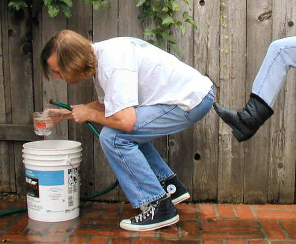
Guys- don’t use your wife’s favorite kitchen measuring cup!
Battery test setup:
Use 3 standard 9-volt batteries (the rectangular type with snap connectors on top.) Using the male and female snaps on top of the batteries, snap all three of them together in a chain. This creates a home-made, portable, 27-volt valve tester. Now touch the valve solenoid wires to the end terminals on your battery chain. The valve should open. Easy. Cheap. And it works great!

Using a chain of 9 volt batteries to open a valve.
Smart Controllers for Irrigation Systems
“Smart Controllers” are controllers that automatically update the watering schedule to allow for changes in water needs throughout the year. So a smart controller will automatically reduce the watering times as the weather gets cooler and less water is needed. Then as the weather begins to warm up, the controller will add more watering time. The way this typically works is that you set the controller for a default maximum watering time, based on the hottest time of year. Then the controller reduces that time amount by a percentage value when less water is needed. There are several methods used by different controllers to determine how much to reduce the watering time. Some controllers may allow for use of more than one method. Here’s a list of the common methods used by smart controllers to determine the watering time:
- Historical. Uses historical weather and water use data for your area to determine what amount of water is required. Typically it only resets the time monthly. While the historic data is not perfect, it still gives significant water savings for most users. You will periodically need to manually override the automatic controller settings, especially if you have unusually hot weather for the month. To setup the controller on some models you simply enter your zip code and it accesses the historic data from it’s memory. On others you have to initially key in the historic data from the user’s manual or a website. Due to the lower cost of this type of smart controller, often it will give you the best financial return on your investment. This is especially true for a small residential irrigation system.
- Historical with a sensor. Uses historical data to determine an initial reduction in watering time, but then further adjusts the time based on a sensor. Typically a temperature sensor is used. If the daily high temperature is higher than the historical data says is normal, it adds more time, if the temperature is lower, it reduces the watering time. This gives more accuracy that the historic data alone will.
- Off-site data. Uses water and/or weather data provided by a remote provider. The controller uses a radio, Internet, or phone connection to obtain the data from either a central data provider, or from a local weather station. Generally there is a subscription charge for the data service and there may also be charges for the telephone, Internet, or radio link. Accuracy is dependent on where the data is obtained from (garbage in, garbage out). If the data comes from a nearby weather station it can be very accurate. If it comes from a central data base of historic data that is expertly manipulated for current conditions it can be very accurate also. So with this type of smart controller you need to ask the provider exactly where the data would come from for a controller installed at your location.
- Weather station. This controller has it’s own weather station that you install with it. It uses real-time data from the weather station to adjust the watering times. It is very accurate if it uses a good weather station.
- Moisture Sensor. A moisture sensor (often more than one) is placed under the irrigation system to measure the actual amount of moisture in the soil. The irrigation time is based on the amount of moisture present. I’m going to get flamed for this, but I wouldn’t be honest if I didn’t tell you that moisture sensors have not been well-accepted by professional turf managers. This is at least in part due to a lack of long-term reliability of the sensor units. There are several types of sensors available. Some require regular maintenance, others do not. There are advantages and disadvantages to each type of sensor. Do some research, as different types of sensors work better with some types of soils than they do with others. Be prepared to spend some time calibrating the sensors and making adjustments. With that said, this is a very accurate method of determining watering times.
Some companies sell add-on equipment, such as moisture sensors, that can be used with any brand of controller to make it “smart”.
With all smart controllers there is an initial shake down period of a few months when the controller will need weekly adjustments. During this time you fine-tune the controller to your actual conditions. After that the controller takes care of the adjustments.
How to Select the Best Rotor-Type Sprinkler
In order to make good decisions about which sprinkler products will work best for you it is necessary to have some basic knowledge of how sprinklers work and what the various options available to you are. Therefore the following is intended to give you the background necessary to understand the terminology used in my reviews.
Sprinklers fall into one of two types based on the method they use to apply water to the ground; spray-type (sprays) or rotor-type (rotors.) Spray-type sprinklers are the type of sprinkler that spray a fixed water pattern similar to how a shower head works. Rotor-type sprinklers use a rotating stream (or multiple streams) of water to apply the water to the ground. Spray-type sprinklers (also called “spray heads” and “sprays”) are typically used for smaller areas. Rotor-type sprinklers (most often simply called “rotors”) are used for larger areas (generally more than 18′ in width.)
Rotor-Type Sprinkler Basics
Rotor is the term used to describe the various sprinklers which operate by rotating streams of water over the landscape. The example which most people are familiar with is the “impact” rotor sprinkler (often improperly called a “rainbird”, Rainbird is the actually the trade name of a sprinkler manufacturer.) The impact sprinkler is mounted on a bearing that allows the entire sprinkler body to spin in circles. It is rotated by the impact of a swinging arm which repeatedly strikes the body of the sprinkler, causing it to rotate slightly each time. You probably know the impact sprinkler best for the distinct sound it makes when operating– tooka, tooka, tooka, tic, tic, tic, tic, tic, tooka, tooka, tooka, etc… You may run into rotor-type sprinklers called “cam drives” or “ball drives”. These are also impact sprinklers, however the impact is caused by either a cam or a ball bearing inside the body of the sprinkler. With ball and cam drive rotors only the nozzle moves. Most of these ball and cam drive sprinklers are no longer sold, but a few, like the Rainbird R-50 (they don’t call it a ball drive, but it is) are still available. While impacts do an acceptable job of irrigating, the jerky motion of the impact drive tends to make them rotate in a less than uniform manner. Thus the impact rotors have now been almost completely replaced by gear-driven rotors, which are very quiet, rotate smoothly, are lower maintenance, and much smaller in size. As with cam and ball drives, only the nozzle on a gear-drive moves. The water moving through the sprinkler spins a turbine, this turns a set of gears, which turn the nozzle. These gear-drive rotors have one or more streams of water which rotate silently across the landscape. The prettiest of these are the multi-stream rotors (or “stream-rotor”) where multiple streams of water rotate over the landscape one after the other. Multi-stream rotors are fascinating to watch but tend to be higher maintenance than the other types of gear-drive sprinkler heads.
Most rotors now come with a set of nozzles rather than a single nozzle. Often these nozzles come attached to what is called a nozzle tree. Just remove the nozzle you want from the tree and install it in the rotor. Save the rest of the nozzles, you may need them later. Multiple nozzles are a big advantage, as you can change to a different size nozzle if needed to help balance your system. Say you have a dry spot between rotors. You might be able to green it up by installing a larger nozzle in the rotors surrounding the dry spot. Some rotors, however, still come with a single, pre-installed nozzle, and some come with stripped down nozzle trees (with only a few of the available nozzle sizes on them.) If you want the whole set of nozzles with these less expensive models, you must purchase them separately. A preinstalled nozzle or limited nozzle tree is common with many of the prepackaged rotors sold at discount stores.
I need to mention a new type of sprinkler, which I am classifying as a rotor since it utilizes a moving stream of water. However, it operates a little different from a traditional rotor. Sometimes called robot sprinklers, these sprinklers direct a stream of water to fall on specific spots. This works something like when you use a hose to water the yard, and you move the nozzle of the hose around to make the stream of water fall on different spots. The size and shape of the area to be watered is programmed into a computer, the computer then controls the sprinklers, telling them where to move the stream and how much water to apply in each spot. Typically they use an electric motor to move the nozzle.
What situations work best with rotor-type sprinkler heads?
Typically rotors are used for sprinkler spacings from 18 feet to 55 feet apart. There are rotors available that can be spaced closer than 18 feet but they are generally not cost effective, as a spray sprinkler will work well at this spacing and cost less. There are also rotors available for spacings farther apart than 55 feet but they are typically only used for golf courses. Most rotors require a lot more water pressure to operate than spray-type sprinkler heads. When selecting a rotor keep Stryker’s Rule in mind; “the water pressure at the rotor head (in PSI) must exceed the distance (in feet) between the heads.”) Thus if you want to space rotors 35 feet apart you will need 35 PSI of pressure at the rotor. (Caution: you will actually need more pressure than 35 PSI to run the system due to pressure loss in the pipes and valves between the water source and the sprinkler. Figure a minimum of 15 PSI more will be required for the pipes and valves.) The small rotors sold for residential use work best at 25 to 35 foot spacings, although with careful design some models can be spaced up to 50 feet apart. As a general rule you should hire a professional designer if you need sprinkler spacings greater than 45 feet. Designing with larger sprinklers requires specialized knowledge as many unique factors must be considered in the design process.
How a Typical Gear-Drive Rotor Works
Water enters the base of the sprinkler. From there it passes through a filter screen and then through a turbine. The water turns the turbine, which powers a set of gears, which rotate the sprinkler nozzle. The water then passes up through the body and exits through the nozzle. Generally the nozzles can be removed and there are numerous nozzle sizes available. At the nozzle there is a radius reduction screw. With most rotors this screw also doubles as the set screw that holds the nozzle in place.
Reducing the Radius and Dealing with Coverage Problems
As the radius reduction screw is turned clockwise the end of the screw comes into contact with the stream of water exiting the nozzle. This distorts the water stream and results in a reduction of the radius. Many people in the irrigation industry refer to this screw as the “break-up screw” because it “breaks up” the water stream. There is a temptation to play around with this screw setting in an attempt to create a better water pattern. However, most modern rotor-type sprinklers are designed to give optimum uniformity with the radius reduction screw not in contact with the water stream. Therefore you should only turn the screw so that it contacts the water stream if you need to reduce the sprinkler radius. Be warned- most people look at the stream of water exiting the nozzle and feel it is not giving a uniform pattern. So they mess with the radius reduction screw trying to get a “better pattern”. Unfortunately, this most often hurts rather than helps. The fact is that without training the average person can’t tell when the water pattern is best by simply looking at it. The moral is if you don’t need to reduce the radius of the stream, then leave the screw in a position where it does not contact the water stream! With that said, there is a situation where the screw does need to be used to break up the water stream to improve the pattern. It occurs when the water pressure (PSI) at the rotor is below the optimum level (indicating in most cases that the system wasn’t designed correctly). You can’t tell if this is a problem by looking at the stream, so look at the ground around the sprinkler. If you have a low pressure problem the sprinkler will create a donut-shaped water pattern on the ground. There will be a very small green area right around the sprinkler head where water leaks from the head. Then there is a dry area for several feet (the donut hole), with a wet area farther out. This creates a pattern on grass shaped like a huge green donut, with a small bit of green in the very center. If this is happening you will need to use the radius adjustment screw to break up the stream so that more water falls closer to the rotor. If there are dry patches located midway between two rotors, but no donut pattern, that usually means the rotors are spaced too far apart, or the radius adjustment screw is too far into the stream. Try backing off the radius adjustment screw until the screw does not contact the water stream. If that doesn’t fix the dry spot try using a larger nozzle size in the rotors adjacent the dry spot. Unfortunately in most cases these simple efforts to fix the problem just result in creating a new problem. For example, using a larger nozzle may cause the pressure to drop and create the previously mentioned donut pattern problem. If new problems are created you will either need to live with dry spots, or spend some serious money making major repairs. Major repairs that are often needed include adding a booster pump to create more water pressure, relocating the rotors so that they are closer together, replacing the pipes with larger size pipes, or a combination of these.
Pop-Up vs. Shrub Style Heads
Rotor bodies come in two basic styles, “pop-up” and “shrub” style. Pop-ups do just what the name implies, the sprinkler body is installed below ground and the nozzle is lifted up above ground on a riser when the sprinkler is operating. After the irrigation is complete, the riser and nozzle are pulled by a spring back down into the sprinkler body. Since the body is typically installed below ground, the sprinkler becomes more or less invisible when it is in the “down” position. This has two advantages. The first is that the sprinkler does not detract as much from the appearance of the landscape. The second advantage is that the sprinkler is not as likely to trip someone, or be damaged by yard care equipment such as lawn mowers.
Recommended Pop-Up Heights
- Bermuda grass, dethatched yearly – use 3” or 4” pop-up.
- Bermuda grass, dethatched less often – use 4” pop-up.
- Fescue, bluegrass, rye grass – use 4”, 5” or 6” pop-up.
- St. Augustine or any grass planted near blowing sand – use 5” or 6” pop-up.
- Low ground cover – use 5” or 6” pop-up.
- Medium height ground cover – use 12” pop-up.
- Shrubs- see discussion below.
The 12 inch bodies work good for taller ground covers and low shrubs. Generally in a landscape design shorter shrubs are used at the edges of planters and larger, taller shrubs are used farther back in the area. So 6 or 12 inch pop-ups at the perimeter will often provide adequate coverage.
Shrub-Style Rotor Sprinklers
Shrub-style sprinkler bodies are mounted above ground level on a vertical pipe. This allows the sprinkler to be elevated above the level of the plants, where it can spray water over them. Shrub-type sprinklers are most often used in areas with tall, dense shrubs. Shrub-type bodies should not be used next to sidewalks, paths, driveways, lawn edges, or anywhere near places people walk or play. This is because the shrub sprinklers may trip people, or worse, someone may fall on one and be impaled (more likely just badly bruised, but the injury is still significant.) Not a pretty thought. For this reason I recommend, as do almost all professionals, that shrub-type spray heads only be used when there is no other option. If you have tall shrubs adjacent to a sidewalk you should consider replacing them with ground cover or lower growing shrubs. I use shrub-style sprinklers mostly on inaccessible hillsides where we are trying to grow plants for erosion control. I typically install them 36″ above ground to reduce problems with people tripping over them or falling onto them. Often I attach them to a large post to make them more visible. One of the arguments often given for using shrub style sprinklers is cost savings. Cost wise, I have found that shrub-style sprinklers are no less expensive than pop-up style bodies once you include the cost of the riser pipe and a stake to keep the sprinkler from wobbling. In order to make a shrub-style sprinkler cost less than a pop-up you must install it within 6″ of ground level. That is the height that makes it most dangerous.
A Brief History of Rotors
Nothing essential to read in this section, it’s provided for those who are curious. The earliest rotors were impact types, and Rainbird was one of the earliest sprinkler companies. Although several companies made similar products, the name Rainbird came to be almost synonymous with impact sprinklers. But impacts had problems in turf areas where pop-up style sprinklers are needed. The drive arms were large and to make a pop-up style of rotor required a huge case (called a bucket) for the sprinkler to retract into. They required a lot of maintenance because grass would grow into the cases and interfere with the arms. These large impact pop-ups are commonly are called “rat traps” in the industry. It was realized that a better solution was needed. In an attempt to create a smaller, closed-case (no exposed moving parts) rotor, cam and ball drive rotors were invented, primarily made by Buckner and a company named Safe-T-Rain. The “Safe-T-Rain” name resulted from the idea that their ball drive rotors were smaller than the impact rotors and presented less of a hazard. Both cam and ball drives also use an impact to turn the sprinkler, but now at least all the moving parts were smaller and internal. But they also wore out quickly and were never really widely accepted by the turf grass industry.
In the mid 70’s the first turbine powered gear-drive sprinklers came along. The Toro and K-Rain companies pioneered the gear drive industry. Toro used a sealed gear train filled with oil and their Toro S700 was the dominant residential size gear-drive for a number of years. They worked very well, but they were really difficult to adjust and the oil-filled gear boxes leaked oil and were expensive to manufacture. About the same time Rainbird introduced the very inexpensive, all-plastic Mini-Paw impact sprinkler. The Mini-Paw was smaller than other impact rotors due to a unique design of the impact mechanism. The Mini-Paw quickly became the biggest seller in the residential rotor market. Unfortunately the Mini-Paws didn’t hold up very well and had the standard impact sprinkler problem of high maintenance costs.
The next innovation in rotor design was water-lubricated gear-drives. These were inexpensive, reliable, and easier to adjust than the Toro models. Hunter, Nelson, and K-Rain quickly came to dominate the entire rotor market. Rainbird desperately needed a sprinkler to compete with these gear-drive rotors, and introduced the R-50, a variation of a ball-drive. The R-50 was a moderate success, but it was hard to adjust and the early models had a lot of maintenance problems. Rainbird then introduced the T-Bird, their first gear-drive rotor. It was essentially a first try and had problems. Finally, on the third try, Rainbird came out with the 3500 and 5000 series gear-drive rotors and belatedly joined the others. Now, finally, all the major irrigation manufacturers have a good gear-drive rotor available.
So what’s next for rotors? The latest innovation is the micro-rotor. This tiny rotor is the size of a spray sprinkler nozzle and fits on a standard spray sprinkler body. This makes it less than half the size of the other rotors, and much less expensive. Developed by the Walla Walla Sprinkler Company and sold under the name MP Rotator, this micro-rotor is a stream rotor type (multiple rotating streams of water.) It is driven by a turbine, but does not have a gear box. To keep the sprinkler rotating at a slow, steady speed it utilizes a sealed gel-filled clutch. The thick gel slows the speed of the nozzle. Rainbird recently introduced a mini-rotor also, and other manufacturer’s will follow. Only time will tell if this will be the next big thing in rotors.
What to Look for in a Good Quality Rotor
I recommend using a gear-drive rotor, or for smaller areas a turbine-driven micro-rotor. Pretty much all of the gear-drive rotors hold up well and perform well. The biggest problem with the gear-drive rotors is adjusting the arcs. Nelson makes the easiest to adjust but has a problem with the cap that covers the adjustment collars coming off. The Toro S700 has the hardest arc to adjust, and everyone else falls someplace in between. The bottom line is to be prepared to get wet when adjusting any rotor! The good news is that every one of the gear-drive rotors currently on the market has essentially the same basic features, so any of them will meet what I would consider the minimum requirements; a 3″ pop-up height, a good wiper seal, stainless steel retraction spring, sturdy plastic body and cap.
Rotor-Type Sprinkler Radius and Spacing
The radius of a rotor-type sprinkler is determined by the water pressure at the rotor inlet and the nozzle used. Most rotors come with several nozzles. More nozzles gives you better control and helps avoid over-watered areas. For a standard rotor you need to use a different nozzle for each arc, so you need one size nozzle for a 1/4 circle, another for 1/2 circle, another for 3/4, and another for full circle. So for even a simple sprinkler system you need at least 3-4 different nozzle sizes! If you also need different radius distances you will likely need even more nozzles. With stream rotors you don’t to use different nozzles for each different arc, so they don’t come with multiple nozzles.
The sprinkler manufacturer will list the radius for each sprinkler nozzle they make on the packaging, or on a separate reference chart (but please read the next paragraph before relying on that data.) Most also have performance data charts on their websites. The radius will vary based on the water pressure and flow, more pressure and flow will result in a larger radius. So for a typical nozzle you will see a table that gives the various radius, pressure and flow combinations for the nozzle (see example below.) If you can’t find the desired radius, get the nozzle with the next size larger radius than you need. The radius can be reduced by means of the radius adjustment screw on the top of the sprinkler nozzle. Some nozzles are designed to spray the water at a very low angle. Be careful of these nozzles, if you have mounded areas or hillsides they may spray water into the ground. It is best only to use low angle nozzles in relatively flat areas.
A big problem with all of the rotors is that they don’t perform as well in actual use as the manufacturer’s performance data tables suggest. The problem is that the radius the manufacturer measures on their indoor test range is not accurate out in the real world where the wind blows. Competition forces them to aim for the largest radius possible at the lowest possible pressure and flow. But the gallonage and pressure have a huge effect on how effectively the water is distributed. For example, a low gallonage, low pressure nozzle is going to be much more effected by wind (even wind so slight you don’t even notice it) than a higher flow, higher pressure nozzle. So you need to be careful. Unfortunately it takes lots of experience to know what works and what does not. Because of competition, the advice you get from the manufacturer’s literature and help lines has, in my opinion, stretched the limits considerably. So, based on my experience I am providing you with nozzle GPM/pressures combinations I recommend you use for various situations. I very strongly suggest that you follow these recommendations. In some cases I have provided more specific recommendations in my reviews. If you don’t follow them you may very well regret it! Many people before you have made this mistake, please don’t join them. Fixing the problem if you use the wrong nozzles can be very expensive! People are really unhappy when I tell them what is needed to fix the problem.
As a general rule I advise against spacing rotors more than 45 feet apart unless you have a professional irrigation consultant design the system. Most contractor’s and “free design services” don’t have the design knowledge to handle a design of this complexity, you need to find a designer with lots of experience. I’m not trying to make anyone look bad, I just have a lot of experience fixing problems on these large radius systems, and have noted that the problems almost always resulted from poor original design. Wide spacings simply bring many difficult design problems with them.
Important! Rotors require what is know in the industry as “head-to-head spacing”. Head-to-head spacing means that the water from one sprinkler must spray all the way to the next sprinkler in all directions- to the right, left and also to the head(s) across from it. This is very important, spacing the sprinkler heads too far apart is one of the most common design errors, and it is almost impossible to go back and correct the problem later without spending tons of money. Simply stated if the radius is 30 feet you need to space the rotors no more than 30 feet apart, less in many cases. The sprinkler design tutorial gives a more in-depth description of the importance of head-to-head spacing. Head-to-head spacing is critical for avoiding dry spots and disease problems. With spacings wider than 45 feet it is often necessary to use spacings even closer than head-to-head.
Matching Precipitation Rates
Standard rotors (the water stream moves back and forth) require a little more design effort. To make this easier I have suggested which nozzles you should use in many of my reviews of specific rotors. In those cases you should simply use the nozzles I recommend. You should also use the free on-line Sprinkler System Design Tutorial when you actually design your system! This is just background information, the tutorial will guide you through the design process step-by-step. However, this information will help you understand why it is important that the rotor you choose to use should come with a large selection of nozzles.
The precipitation rates for standard rotors are not matched, so you must select the right nozzle size for each rotor based on the radius, pattern, and flow of the various nozzles available. Here’s an example of a performance chart for a typical standard rotor. (Don’t actually use this chart, it is just a sample! Each brand and model has it’s own chart, you need to use the correct chart.)
Sample Rotor Nozzle Performance Chart
| Nozzle No. | 30 PSI | 40 PSI | 50 PSI | 60 PSI |
|---|---|---|---|---|
| 1.0 | 32′ – 1.3 GPM | 33′ – 1.5 GPM | 34′ – 1.6 GPM | 35′ – 1.8 GPM |
| 2.0 | 37′ – 2.4 GPM | 40′ – 2.5 GPM | 42′ – 3.0 GPM | 43′ – 3.3 GPM |
| 3.0 | 38′ – 3.6 GPM | 39′ – 4.2 GPM | 41′ – 4.6 GPM | 42′ – 5.0 GPM |
| 4.0 | 43′ – 4.4 GPM | 44′ – 5.1 GPM | 46′ – 5.6 GPM | 49′ – 5.9 GPM |
The chart above shows four nozzles (for many rotors there will be more nozzles available.) For each nozzle it gives the radius and GPM combinations that result at different water pressures. Remember this is the water pressure at the sprinkler, which will be less than the water available water pressure due to pressure lost in the pipe and valves.
Let’s consider a 60 foot x 60 foot square lawn area (see image below.) Nine rotors would be required to water this area as follows: In each of the four corners there would be a 1/4 circle rotor (4 total). At the mid-point of each side there would be a half circle rotor (4 total). In the exact center of the lawn there would be a single full circle rotor. Each rotor would need a radius of 30 feet. This would provide the desired head-to-head spacing.
Rotor Spacing Example for 60′ x 60′ Lawn
(Using 30′ Radius Rotors)
Yes, this is how many rotors you need to water a 60 foot square lawn! No need to write and ask me if I made a mistake. Nope, I don’t get kick-backs from the sprinkler companies for helping them sell more sprinkler heads. There are a number of good reasons for all the overlap, if you really are interested you can take a couple of classes at your local university in physics and hydraulics. OK, I’m guessing that doesn’t sound very interesting to you, so let’s just move on.
As you recall from the description of a standard rotor, the rotor shoots a stream of water that rotates one way around the rotor, then reverses back the other direction, covering the same area again (except for a full circle rotor, which just moves continuously in a circle.) This back and forth motion creates a problem- since all the rotors turn at the same speed. So in the time it takes the full circle rotor to make one complete rotation, the 1/4 circle rotor will have gone back and forth over the same area 4 times. So if you use the same size nozzle in all the rotors the area watered by the quarter circle rotor would have 4 times more water applied to it than the area watered by the full circle rotor. This will not work! The area around the corners would turn to mud while the area in the center of our lawn would be dry! Therefore, to compensate we use a smaller nozzle in the corners and a larger one in the center. The full circle nozzle will need to have a GPM four times higher than that of the quarter circle. Using our 60 foot square lawn and the Sample Rotor Nozzle Performance Chart above we would select the following nozzles:
| Arc | Nozzle | PSI | Radius | GPM |
|---|---|---|---|---|
| 1/4 circle | Nozzle #1 | 30 PSI | 32′ radius | 1.3 GPM |
| 1/2 circle | Nozzle #2 | 30 PSI | 37′ radius | 2.4 GPM |
| 3/4 circle | Nozzle #3 | 30 PSI | 38′ radius | 3.6 GPM |
| full circle | Nozzle #4 | 30 PSI | 43′ radius | 4.4 GPM |
One thing you will notice is that these nozzles are not a perfect solution. To be perfect, all the radii would be identical and the GPM values would be exact multiples of each other (ie; all radii would be 30 feet and GPM values would be 1.1, 2.2, 3.3, and 4.4 GPM.) Unfortunately perfection is not attainable, so we must settle for the next best thing. In this case the GPM values are close enough to being multiples of each other. Because the radii are all larger than we need, it will be necessary to reduce the radius of each rotor after it is installed by using the radius adjustment screw. Now you can understand why a rotor that includes a lot of nozzles is better than one that only includes one nozzle. If you go to a typical discount retail store you will find a lot of rotors that only come with one nozzle. Now you know why that is not such a good deal for most yards. No doubt a lot of you are thinking to yourself, “so that’s why the middle of my yard is as dry as an old bone and the corners are swamps!”
Stream rotors have matched precipitation rates, so you don’t have to deal with the different nozzles for different arcs problem. If you are designing with them you will use the same nozzle for all the sprinklers that have the same radius. A chart provided by the manufacturer will tell you the GPM for each rotor based on the pattern used (ie; quarter circle, half circle, full circle.) This makes designing with stream rotors a bit easier than with standard type single stream rotors. Select stream rotor nozzles based on the radius desired. Most stream rotors do not have a radius adjustment feature, so the radius can’t be changed except by changing the nozzle. Here’s an example of a nozzle chart for a stream rotor:
Sample Stream Rotor Nozzle Performance Table
| Nozzle No. | PSI | Radius | 90° | 180° | 270° | 360° |
|---|---|---|---|---|---|---|
| 01 | 35 | 16 ft | 0.57 | 1.14 | 1.71 | 2.28 |
| 02 | 35 | 21 ft | 0.72 | 1.44 | 2.16 | 2.88 |
| 03 | 35 | 28 ft | 1.36 | 2.72 | 4.07 | 5.43 |
From the nozzle chart you start by selecting the radius you want. The table tells you the pressure you will need and the GPM that the sprinkler will require. So if you need a 21 foot radius you would select nozzle #02. The chart then tells you that you will require 35 PSI at the rotor and for a half circle pattern (180°) the flow used by the rotor will be 1.44 GPM.
Special Situations
Most rotor-type sprinklers are available with a number of optional features. Here are some situations where you should consider using a rotor sprinkler with optional features.
Slopes & Check Valves. If your yard is sloped you should use sprinklers with built-in check valves. An elevation change that exceeds the depth of your pipe is enough to make the use of check valves advisable. In other words, if one side of the yard is more than a foot lower than the other, and you plan to bury the pipes less than a foot deep, you should use check valves. I use them on all my projects as the default. Most manufacturer’s built-in check valves will work up to an elevation difference of 10 feet height. If the elevation difference between sprinklers is greater than 10 feet you will need to add an additional adjustable low-drainage prevention check-valve under the sprinkler. The purpose of the check valves is to prevent the water from draining out of the pipes through the lowest sprinkler head each time the water is turned off (this is called “low-head drainage”.) Low head drainage creates mud pits around the lowest heads, and also allows water to drain onto sidewalks causing algae and moss to grow. Plus each time you start up a valve zone the sprinklers will sputter and spit as the air is pushed out, which is bad for the pipes, hard on the sprinkler, and wastes water.
If you use check valves and you are in a cold winter area where you winterize your sprinkler system, you need to have your sprinkler system winterized by blowing the water out of pipe with air. Another option is to remove the check valves before you winterize the system, however this is a lot of work. The check valves trap the water in the pipes and the sprinkler heads where it will freeze and break the pipes and the sprinkler heads.
Play areas. When using rotors in play areas you should use rotors with rubber covers. The rubber cover helps reduce injuries caused when someone falls on the sprinkler.
Extremely sandy soil. Some rotors are available with stainless steel sleeves around the pop-up riser. This helps keep the riser from becoming scratched by sharp sand particles. Deep scratches in the plastic can prevent the riser from easily moving up and down. Generally this is not a big problem except in very sandy areas.
Recycled (also called reclaimed) water. When using recycled water the rotor should be equipped with an optional purple-colored cap. Recycled water is usually treated sewage or grey water (wash water.) Many cities are now installing separate water systems that carry recycled water for use with irrigation systems, especially in areas where water is scarce. In general, human contact with recycled water should be avoided. The purple color is the universal identifier of the presence of recycled water.
How to Select the Best Spray-type Sprinkler
In order to make good decisions about which products will work best for you it is necessary to have some basic knowledge of how sprinklers work and what the various options available to you are. Therefore the following few paragraphs are intended to give you the background necessary to understand the terminology used in my reviews. The background information below is much more in-depth than that in the tutorials, so even if you have read the tutorials you should still look through this page.
Fixed Spray-Type Sprinkler Basics
Sprinklers fall into one of two types based on the method they use to apply water to the ground; fixed spray-type (sprays) or rotor-type (rotors.) Spray-type sprinklers are the type of sprinkler that spray a fixed water pattern similar to how a old-fashioned shower head works. Rotor-type sprinklers use a rotating stream (or multiple streams) of water to apply the water to the ground. Spray-type sprinklers are also called “fixed spray heads”, “spray heads” and often just plain “sprays”. Most of the professionals I know call them “spray heads”, and you will note that is the term I use also. They are typically used for smaller size areas. Rotor-type sprinklers are used for larger areas (generally more than 18′ in width.)
Where should spray heads be used?
Spray heads work best for smaller areas and areas with tight, curving edges. I like to use them for anything less than 25 feet wide. Although rotors are available for areas as narrow as 18 feet, spray heads tend to be more economical in these smaller areas than rotors. Another advantage of spray heads is their relative simplicity. There is not a whole lot to go wrong with one. By far the most common problems result from clogged nozzles, a problem that can be almost totally eliminated by flushing the pipes thoroughly prior to installing the spray heads and installing a filter on your sprinkler system. (Install the filter upstream of the automatic sprinkler system valves so the valves benefit from filtered water too!) Although most spray heads come with a small filter screen that installs under the nozzle, in my opinion these filters are not sufficient. I recommend installing a 100 mesh filter at the water source for ALL sprinkler systems.
How a Typical Spray-Type Sprinkler Works
Water enters the base of the sprinkler and passes up through the body to the nozzle. On the way to the nozzle the water passes through a filter screen. As previously mentioned I do not suggest that you rely on this screen for filtration, consider it a backup to your sprinkler system filter. Do not remove the filter screen, some spray type sprinklers will not work properly without the screens! After passing through the screen the water enters the nozzle and passes through a small valve. This valve is operated by a screw on top of the nozzle, which is known as the “radius adjustment screw”. As you turn the screw the valve closes slightly. This causes the water to speed up as it tries to force it’s way through, resulting in an increase in turbulence and friction. This turbulence and friction causes a drop in the water pressure. The pressure drop in turn causes the radius of the sprinkler to be reduced. From the radius adjustment valve the water continues up into the nozzle and is sprayed up against a plate or through a small slit(s), which causes the water to fan out as it leaves the nozzle. This is what creates the fan-like spray pattern typical of a spray head. The shape and size of the plate or slit is what determines the nozzle pattern and angle. Some spray nozzles have adjustable plates or slits that allow the spray arc to be adjusted.
A typical spray head consists of two separate parts, a body and a nozzle. Often these are sold separately, but sometimes retail stores package them together. Typically various different nozzles are available, anywhere from just a few different patterns and radii combinations, up to hundreds of variations. In most cases all of a manufacturer’s nozzles will fit on all of their spray head bodies.
Pop-Up vs. Shrub Spray Heads
The bodies come in two basic styles, “pop-up” and “shrub” style. Pop-ups do just what the name implies, the sprinkler nozzle is attached to a riser which lifts the nozzle up into the air when the sprinkler is operating. After the irrigation is complete, the riser and nozzle drop back down into the sprinkler body. Since the body is typically installed below ground, the sprinkler becomes more or less invisible when it is in the “down” position. This has two advantages. The first is that the sprinkler does not detract as much from the appearance of the landscape. The second advantage is that the sprinkler is not as likely to trip someone, or be damaged by yard care equipment such as lawn mowers.
Recommended Pop-Up Heights
- Bermuda grass, dethatched yearly – use 3” or 4” pop-up.
- Bermuda grass, dethatched less often – use 4” pop-up.
- Fescue, bluegrass, rye grass – use 4” or 6” pop-up.
- St. Augustine or any grass planted near blowing sand – use 6” pop-up.
- Low ground cover – use 6” pop-up.
- Medium height ground cover – use 12” pop-up.
- Shrubs- see discussion below.
The 6 inch height bodies are the primary height I use for my projects in both lawn, shrub, and most ground cover areas (I use a lot of low growing ground covers with 4-6 inch mature height.) The 12 inch bodies work good for taller ground covers and low shrubs. Keep in mind that with shrubs you don’t always need to throw the water over the top of the shrub. When the shrubs are first planted they are small and a 6″ height will spray over them. As the shrubs grow they begin to block the spray, but by this time the shrub has developed a good root system and will seek out the water. Generally in a landscape design shorter shrubs are used at the edges of planters and larger, taller shrubs are used farther back in the area. So 6 or 12 inch pop-ups spaced 10 to 12 feet apart at the perimeter will usually provide adequate coverage.
Shrub-Style Spray Sprinklers
Shrub-style sprinkler bodies are mounted above ground level on a vertical pipe. This allows the sprinkler to be elevated above the level of the plants, where it can spray water over them. Shrub type sprinklers are most often used in areas with tall, dense shrubs. Shrub type bodies should not be used next to sidewalks, paths, driveways, lawn edges, or anywhere near places people walk or play. This is because the shrub sprinklers may trip people, or worse, someone may fall on one and be impaled (more likely just badly bruised, but the injury is still significant). Not a pretty thought. For this reason I recommend, as do almost all professionals, that shrub type spray heads only be used when there is no other option. If you have tall shrubs adjacent to a sidewalk you should consider replacing them with ground cover or lower growing shrubs. I use shrub style sprinklers mostly on inaccessible hillsides where I am trying to grow plants for erosion control. I usually install them 36″ above ground to avoid problems with people tripping over them or falling onto them. One of the arguments often given for using shrub style sprinklers is cost savings. Cost wise, I have found that shrub style sprinklers are no less expensive than pop-up style bodies once you include the cost of the riser pipe and a stake to keep the sprinkler from wobbling. In order to make a shrub style sprinkler cost less than a pop-up you must install it within 6″ of ground level. That is the height that makes it most dangerous. Your homeowner’s insurance rates will likely go through the roof if someone trips on a sprinkler and files a claim for injuries. This will be far more expensive than the cost would have been to use pop-up sprinklers!
Spray-Type Sprinkler Radius
The radius of a spray-type sprinkler is determined by the nozzle used. The sprinkler manufacturer will list the radius for each sprinkler nozzle on the packaging, a separate reference chart, or their website. The radius will vary based on the water pressure, more pressure will result in a larger radius. So for a typical nozzle you will see a table that gives the various radius, pressure and flow combinations for the nozzle (see example below.) Most spray head nozzles have a radius between 4-15 feet, some are claimed to have a radius as great as 21 feet, but I would urge caution using a radius over 15 feet. It’s a physics problem, water simply doesn’t spray further than 15 feet very well or evenly. When selecting a nozzle, look for one with a radius as close to your desired radius as possible. If you can’t find the desired radius, get the nozzle with the next size larger radius than you need. The radius can then be reduced by means of a radius adjustment screw on the top of the sprinkler nozzle. As the adjustment screw is closed, the water pressure at the nozzle is decreased, this results in the radius and flow of the sprinkler being reduced. For example, if you wanted to water a 14 foot wide area you would install a 15 foot radius spray head and use the radius reduction screw to reduce the radius to the desired 14 feet. With most nozzles the radius can be adjusted down to almost nothing, however I don’t recommend reducing it by more than about 40% when using the radius adjustment screw. Further reduction can cause coverage and operation problems. Often times a nozzle with a severely reduced radius will stop working on warm days. This is because the heat causes the radius reduction screw to expand, which causes the flow to be completely shut off. One last thing to watch for when selecting a nozzle is the angle of spray. Some nozzles are designed to spray the water at a very low or even flat angle. Be careful of these nozzles, if you have mounds or hillsides they may spray the water into the ground. It is best only to use low angle nozzles in flat areas.
Spray-Type Sprinkler Spacing
As a general rule I advise against spacing spray-type sprinklers more than 18 feet apart. Spacing them farther than that often gives unsatisfactory results. Spray heads require what is know in the industry as “;head-to-head spacing”. This means that the water from one sprinkler must spray all the way to the next sprinkler in all directions– to the right, left and also to the head across from it. This is very important, spacing the sprinkler heads too far apart is one of the most common design errors, and it is almost impossible to go back and correct the problem later without spending tons of money. The sprinkler design tutorial gives a more in-depth description of the importance of head-to-head spacing. Head-to-head spacing is critical in lawn areas for avoiding dry spots and disease problems. In shrub and ground cover planting there is more room for fudging, you can generally space the heads at up to 60% of their diameter of water throw. Examples: Using a 15′ radius head for lawn areas you should not exceed 15′ between sprinklers. Using 15′ radius spray heads for shrub areas you should not exceed 18′ (30′ diameter x 0.6) between sprinklers.
Sample Spray Nozzle Performance Table (this sample is for a Toro nozzle)
| Pattern | Part No. | 20 PSI | 30 PSI | 40 PSI | 50 PSI |
|---|---|---|---|---|---|
| 12Q | 11′ – 0.40 GPM | 12′ – 0.50 GPM | 13′ – 0.60 GPM | 13′ – 0.63 GPM |
Example: From the chart above you can see that this nozzle at 30 PSI will have a radius of 12 feet and a flow of 0.50 GPM (gallons per minute). If you wanted to operate this nozzle at 25 PSI you would need to extrapolate the data from the chart. For example for this nozzle 25 PSI would give 11.5′ radius and 0.45 GPM flow.
Reducing the radius of a nozzle.
As previously noted you can reduce the radius of most nozzles using the radius reduction screw. This allows you to use the nozzle in a smaller area. A common question I am asked is what happens to the flow of the nozzle when you decrease the radius? The answer is that the flow (GPM) is reduced, but not by much. In most cases you can just ignore it and use the full radius flow. If you really want to find out how much the flow would be reduced, simply refer back to the manufacturer’s performance chart for that nozzle. As previously mentioned, the radius reduction screw works by reducing the water pressure in the nozzle. If you look at a performance chart it will give you the radius at various pressures. Make sure you are using the right chart for the nozzle you plan to use. Find the radius on the chart that you plan to create using the radius reduction screw. The chart will show you the flow the nozzle uses at that radius.
Example: Let’s say you install the nozzle shown in the table above in a situation with 30 PSI, but you only want it to throw 11 feet. You would use the radius reduction screw to reduce the radius to 11′. According to the chart at an 11 foot radius the nozzle would use a flow of 0.40 GPM.
Matched Precipitation Rates
Most spray heads now have what are called “matched precipitation rates”. Matched precipitation (ppt) rate nozzles mean that the nozzles can be mixed and matched on the same sprinkler zone without concern that one might apply more water than another. Back in the bad old days, only nozzles with the same radius were matched. So you had to use all the same radius nozzles on each valve circuit. But now with matched ppt rate nozzle sets, you can use the radius that works best. So you can use 8 foot, 12 foot, 15 foot, and strip nozzles on the same valve circuit and you will still get nice uniform coverage (provided you don’t exceed head-to-head spacing, that is!) You don’t even begin to know how much easier this makes designing a sprinkler system! There are two exceptions you need to keep in mind however. First, only those nozzles in a manufacturer’s set that are labeled “matched precipitation” are matched. Most manufacturer’s also make nozzles that are not matched to the others. So make sure they are labeled “matched precipitation”. Second is that all the nozzles must be made by the same manufacturer. Each manufacturer uses a different precipitation rate as the default one for the nozzles to match. So don’t mix manufacturer A’s nozzles together with manufacturer B’s nozzles on the same valve zone, even though they both may be labeled “matched ppt”.
Misting and Fine Tuning:
All spray-type sprinklers will mist and waste water if the water pressure exceeds the levels listed in the performance data tables. Some misting is normal. To determine if the misting is excessive adjust one sprinkler as follows:
- Turn the radius reduction screw on the nozzle until the radius is less than head-to-head coverage.
- Now open it back up until head-to-head coverage is obtained.
The sprinkler is now operating efficiently, and you will be able to observe the normal level of mist. If all the heads are misting too much, you should use the flow control on the valve rather than the radius reduction screws to reduce the misting. Simply follow the steps above, but close and open the valve flow control rather than the radius reduction screw. If only a few are misting, use the radius reduction screw on the sprinkler.
Special Situations
Most spray-type sprinklers are available with a number of optional features. Here are some situations where you should consider using a spray-type sprinkler with one of these optional features.
- Slopes. If your yard is sloped you should use sprinklers with built-in check valves. An elevation change that exceeds the depth of your pipe is enough to make the use of check valves advisable. So if you are installing the pipe 12″ deep, and one side of the watered area is 18″ higher than the other, you should use check valves. I use them on all my projects as the default, they aren’t very expensive. Most manufacturer’s built-in check valves will not work if the elevation difference is greater than 10 feet. If the elevation difference between sprinklers is greater than 10 feet you will need to add a separate adjustable low-drainage prevention check valve under the sprinkler. For built-in check valves look for sprinklers with the “CV” feature in my list of sprinkler features.
- Radius under 6 feet. If you are reducing a nozzles radius to less than 6′ consider using an optional Pressure Control Disc to reduce the radius rather than using the built-in radius reduction screw. This does not apply to nozzles that are designed to spray less than 6 feet such as strip sprays and short radius nozzles. It only applies when you plan on using the radius reduction screw to reduce the radius of a nozzle that is designed to throw more than 6 feet. Look for sprinklers with the “PCD” feature in my list of sprinkler features.
Optional Features
Check Valves (CV). The most popular option for spray heads are built-in check valves. If your sprinkler system is being installed in an area where the elevation change exceeds the depth you are burying the pipe you should probably use sprinklers with this feature. Example; if the elevation change is 10 inches and you are burying the pipes 6 inches deep, you should use check valves. But in this same situation if you were burying the pipes 12 inches deep you would not need them.
The check valve prevents water from draining out of the pipes through the sprinkler head after the valve closes. When the water drains out of the pipes it is replaced with air. The next time you turn on the sprinklers this air must be expelled from the pipes, so for the first couple of minutes the sprinklers spit and spew air. This puts a lot of stress on the pipe and the sprinklers. As the water rushes into the pipes it slams into the ells and tees where the pipe changes direction. The air also messes up your uniformity as some sprinklers are watering the lawn while others are just blowing air out! The last problem is that the water that drains out of the sprinkler heads after the valve closes has to go somewhere. So it either runs across a sidewalk or driveway and grows moss and mold, or it makes a big mud puddle around the sprinkler head.
There is one large misunderstanding in the industry about check valves that you should be aware of. Many people, even professionals, erroneously believe that check valves will prevent water from running out of the heads if the valve leaks. This is absolutely not true. If the valve is leaking when it is closed, water will still run out of the lowest head, even if you have check valves installed in the head. This is because the water leaking from the valve is pressurized, and the pressurized water has sufficient energy to force open the check valves. The bottom line is that if you have a leaky valve, the water is going to come out of one of the sprinkler heads and check valves will not stop that. Now this is such a prominent “urban sprinkler legend” that I know a few people out there are going to want to argue with me about it. So before you fire off an angry email to me please test it out yourself. Install a valve zone with check valves on all the heads. Then open the valve just a tiny bit, just as if it were leaking. Now check out the water leaking out of the heads!
Pressure Control Discs. These small disks fit into the bottom of the nozzle or are built into the screen. They are essentially a rubber disk with a small hole in it that restricts the water flow. They control the water pressure and flow into the nozzle. As the water pressure presses against the soft rubber of the disc, the disc deforms and the hole gets smaller, thus reducing the flow through it. They are very handy for reducing the radius of a spray-type sprinkler as they work much better than the radius reduction screws on the nozzles. The sprinkler manufacturer will have a chart showing which disc to use with each nozzle to give the exact radius you need. You will probably need to go to an irrigation specialty stores to purchase these. The Pressure Control Discs can be easily retrofitted into existing sprinklers.
Other available features and options for spray-type sprinklers are described on the spray sprinkler listing page.
Irrigation Water Filtration & Filter Recommendations
Why a Filter?
Water filtration is important for all irrigation systems. Now before someone argues with me, yes, some sprinkler systems are used to spread solids, such as treated sewage, for disposal. But even those in my experience have incorporated some form of filtration upstream of the system to prevent solids which are too large from entering the system.
Filters can help extend the life of, and lower the maintenance on, your sprinkler system. For drip systems they are a necessity to prevent emitters from becoming plugged. Even if small sand particles can pass through your system without clogging it, they cause wear on the equipment. Automatic valves contain very small water passageways in them which can become plugged resulting in the valve failing to either open or close. A small grain of sand caught in a spray nozzle can result in a dry, dead spot in a lawn.
While sand is probably the first thing most people think needs to be filtered out of the water, organic materials can be just as important to remove. Algae can grow inside the system, especially in drip tubes. Another situation occurs when a small piece of organic matter snags somewhere in a valve, fitting, emitter, or sprinkler. The organic matter by itself may not be large enough to be a problem. But soon another piece comes along and gets caught in the first. Then a very small grain of sand that would normally have passed through the system without problems becomes caught in the organic matter. Soon a large build-up of crud forms and the flow is blocked. Have you ever had the hose on your vacuum cleaner clog up with a wad of hair, small objects, and dirt? Each one of those objects went into the hose, so they should have made it through to the canister. But they didn’t because they all got caught together. The same thing happens in your irrigation system. How about a small fish or a clam? They go into your system when they are small (often as eggs) and once in there they grow! Laugh if you want, but I’ve seen it many times! Freshwater clams are very common in city water systems. That’s right, there’s a very good chance that every time you get a drink from the faucet you’re drinking clam water! Yuck… (but be realistic, has it killed you yet? Or perhaps you’ve never eaten clam chowder? Or maybe you should take a look in your cat or dog’s bowl at what THEY drink without getting sick. The truth is that your body processes dirt much better than your irrigation system does!)
Types of Filters
Filters are broken down into different categories dependent upon the method used to filter the water. A brief description of the most common types follows.
Screen filters:
Screen filters are probably the most common filters and in most cases the least expensive. Screen filters are excellent for removing hard particulates from water, such as sand. They are not so great at removing organic materials such as algae, mold, slime, and other unmentionables! These non-solid materials tend to embed themselves into the screen material where they are very difficult to remove. In other cases they simply slide through the holes in the screen by temporarily deforming their shape.
Screen filters are cleaned by flushing them with a stream of water or removing the screen and cleaning it by hand. Depending on the flush method used you will probably have to periodically hand clean the screen to remove garbage not removed by flushing. Several methods of flushing are common. The simplest is a flush outlet. The outlet is opened and it is hoped that the debris washes out of the flush outlet with the water! An improved variation on this is the directed-flow flush. Again a flush outlet is opened, but in this case the structure of the filter is designed so that the flush flow rushes over the face of the screen sweeping the debris along with it. Somewhat like hosing off a sidewalk with a strong stream of water. This is the most common method found in inexpensive filters. The most effective method of flushing is the backwash method, but these filters are typically more expensive. In this method the flush water is forced backwards through the screen for a very effective cleaning. This is accomplished by either using two filters side-by-side (the clean water from one is used to flush the other) or by “vacuuming” the screen with a small nozzle which is moved over the screen by a mechanism in the filter, “sucking” the debris off of it. (Although it is referred to as vacuuming it is really a form of backflush. The water is forced backwards through the screen by the water pressure in the system, not by a true vacuum.)
Cartridge Filters:
Cartridge filters are essentially a variation of the other types listed here, depending on what the cartridge is made of. Most cartridges contain a paper filter which works just like a screen filter. Most also remove organics well because the paper texture is rough enough to snag the organic matter. While some cartridges can be washed, most of them you simply replace when dirty.
Media Filters:
Media filters clean the water by forcing it through a container filled with a small, sharp edged, “media”. In most cases the media material is uniform sized, crushed sand. The water passes through the small spaces between the media grains and the debris is stopped when it can’t fit through these spaces. Media filters are best for removing organic material from the water. This is where the importance of the sharp edged media comes into play. These sharp edges snag the organics which would otherwise slime and slither their way through the small spaces. This is why it is important to use sharp media. Whenever someone tells me their media filter doesn’t work my first question is always “where did you get your media material for the filter?” Their answer is almost always something to the effect of “uh…, I just used some sand from the creek up the road, why?” River, beach, and creek sand tend to have rounded, soft edges and are not suitable at all for media filters! Media filters are the type of filters most commonly used for high volume cleaning of water from rivers and lakes. They are used by both large farms and municipal water systems. They most often are 3 to 6 foot diameter rounded tanks sitting on short legs, and are almost always in groups of two or more. I’ve seen municipal water systems with media filters that are over 12 feet tall and 10 feet in diameter! They tend to be a wee bit large and heavy for the average homeowner! Media filters are cleaned by backflushing. The force of the water going backwards through the filter lifts and separates the media which frees the debris and washes it out through a flush valve. Because a small amount of media is often washed out too, it is necessary to periodically add some more to the filters. Because sand is not easily flushed out of them, media filters are not good for situations where the water contains a lot of sand. The sand will not flush out and soon the filter will be completely filled with sand which you will have to remove by hand. Media filters must be carefully matched to the system flow rate for proper operation. Always consult the media filter manufacturer’s literature for proper sizing procedures!
Disk Filters:
Disk filters are a cross between a screen filter and a media filter, with many of the advantages of both. Disk filters are good at removing both particulates, like sand, and organic matter. A disk filter consists of a stack of round disks. The face of each disk is covered with various sized small bumps. A close up view of the bumps reveals that each has a sharp point on the top of it, somewhat like a tiny pyramid. These bumps are very small, thus a typical disk looks a lot like the old vinyl 45 RPM records! Because of the bumps, the disks have tiny spaces between them when stacked together. The water is forced between the disks, and the particulates are filtered out because they won’t fit through these gaps. The organics are snagged by the sharp points on the bumps. For automatic cleaning of the filter the disks are separated from each other which frees the debris to be flushed out through a flush outlet. For less expensive disk filters you must remove the disks and hose them off.
Centrifugal Filters:
Also known as “sand separators”, centrifugal filters are primarily for removing particulates, such as sand, from the water. They are great for situations where a lot of sand is present in the water as they don’t clog up nearly as quickly as other types of filters. The dirty water enters the filter where it is swirled around the inside of a cylinder. The centrifugal force causes the sand particles to move to the outside edge of the cylinder where they gradually slide down the side to a holding tank at the bottom. Centrifugal filters are reasonably inexpensive, very simple, and are very effective for removing sand from water. Because many wells pump sand up along with the water you will often see a centrifugal filter installed on a large well. Some centrifugal filters are designed to be installed inside the well. These typically are attached to the bottom of a submersible pump. It is not unusual for a very small amount of sand to pass through a centrifugal filter. For drip irrigation systems I always add a “backup” screen filter when using a centrifugal filter as a safety precaution. A centrifugal filter used in combination with a media filter after it is an excellent combination. The centrifugal pulls out the sand, the media filter then removes the organics. This combination is very often used in municipal water treatment, where a third activated charcoal filter may be added to remove chemicals. Note that the centrifugal filter selection must be carefully matched against the system GPM or the filter will not work correctly. Always consult the manufacturer’s sizing guidelines when designing a centrifugal filtration system for your irrigation system.
Tutorial continues below…
Filter Recommendations
So which filter to use? There is no fixed answer. Your budget, water quality, and availability of the filter and parts must all be considered. Screen filters are generally the least expensive. If you have a city water supply with nothing more than a periodic grain of sand or flake of rust in it, a screen filter will be fine in most cases. Sometimes a combination of more than one type of filter will be needed. For a smaller size system a disk filter would remove both sand and organics, but you might need to frequently clean it! Here are some suggestions based on the source of your irrigation water:
| Water Source | Suggested Filter Types |
|---|---|
| Municipal Water System | Screen Filter, Centrifugal Filter, or Disk Filter. |
| Well | Screen Filter, Centrifugal Filter, or Disk Filter. |
| River or Creek | Disk Filter, Media Filter and Screen Filter, Centrifugal and Media Filter. |
| Pond or Lake | Disk Filter, Media Filter and Screen Filter, Centrifugal and Media Filter. |
| Spring or Artesian Well | Screen Filter, Centrifugal Filter, or Disk Filter. |
| Organic material in water | Disk Filter, Media Filter and Screen Filter, Centrifugal and Media Filter. |
| Sand in water | Screen Filter, Centrifugal Filter, or Disk Filter. |
How much Filtration do you need?
What we are asking here is what’s the smallest size of particle that needs to be removed from the water by the filter? The amount of filtration you need is dependent to a large degree on what type of irrigation you have. For example, drip irrigation systems need a much higher degree of filtration in order to protect the emitters from plugging. For most applications the amount of filtration is measured by the “mesh size” of the screen or maximum size in “microns” of an object that can pass through the filter. There is a mesh vs. micron conversion table at the bottom of this page.
You always want to use the highest level of filtration that is practical. Even if your sprinkler system can easily handle a fairly good size grain of sand without clogging, removing that sand grain is still advantageous as it will eliminate the wear on the system caused by the sand grain as it passes through. The balancing factor is that the more particles removed the more often the filter clogs up and needs to be flushed. Excessive flushing can waste water and energy, so a trade off is necessary.
Rule of Thumb Guidelines
Drip Systems:
The drip emitter manufacturer will specify in their literature the level of filtration required. I almost always take it one level greater. (That is, I remove even smaller particles than they recommend.) I generally never use anything less than 100 mesh or 150 micron.
Sprinkler Systems:
A 70 mesh filter will remove most particles capable of plugging a sprinkler nozzle, however, I like to use a 100 mesh (150 micron) and often use a 150 mesh (100 micron) filter in order to also remove the particles that can cause wear on the system and damage the valves.
All Irrigation Systems:
Bottom line- I would suggest using at least a 100 mesh (150 micron) screen or equivalent in the filter. I suggest you run the water through a filter before it reaches the control valves. Small grains of sand are one of the most common causes of control valve failure, especially when using the standard electric solenoid valves used on most irrigation systems. My experience is that the savings in valve repairs will pay for the cost of the filter over the next 5 years. With a cost benefit like that it is pretty hard to argue against installing a filter!
Approximate Filter Size Equivalents
| Micron | mm | Mesh |
| 800 | 0.8 | 20 |
| 500 | 0.5 | 30 |
| 300 | 0.3 | 50 |
| 250 | 0.25 | 60 |
| 200 | 0.2 | 75 |
| 180 | 0.18 | 80 |
| 150 | 0.15 | 100 |
| 130 | 0.13 | 120 |
| 100 | 0.1 | 150 |
| 100 | 0.1 | 155 |
| 80 | 0.08 | 200 |
| 50 | 0.05 | 300 |
| 40 | 0.04 | 350 |
| 30 | 0.03 | 500 |
| 25 | 0.025 | 600 |
| 15 | 0.015 | 1000 |
The values in the table above are rough equivalents. While the Micron is a standard metric measurement, the term Mesh is rather subjective, especially for values over 300. For example, I’ve seen both 500 mesh and 700 mesh screens that have equal filtration, that is, they both filter out particles down to 30 microns in size. The problem is related to the size of wire from which the screen is manufactured. The mesh designation is based on the number of wires in one linear inch of the screen. So two screens can have the same mesh, but if one is made with thicker wire than the other, the one with thicker wire will have smaller openings between the wires. Therefore, micron is a much more accurate measurement for use in determining the size of particle that can (or can’t!) pass through a filter.
Irrigation Backflow Preventers

Backflow Preventer Basics:
Backflow Preventer definition: A device that allows water to go through it in one direction, but prevents it from going backwards in the opposite direction.
A backflow preventer is like a one-way gate for water. Most backflow preventers are used to keep unsafe water from reversing flow and entering the clean water supply. Backflow preventers can be as simple as a single check valve that closes when water flow reverses. Using a simple check valve as a backflow preventer might be considered the equivalent of a turnstile at a store entrance. It is not very reliable, even a small amount of effort will overcome it. A more elaborate backflow preventer can be a complicated device that consists of multiple check valves, water release valves, air vents, and/or systems to allow it to be tested to assure it is working properly. This kind of backflow preventer might be the equivalent of an airport exit security checkpoint with one-way gates and a guard.
You should have a backflow preventer on your irrigation system if your water comes from a “potable” (drinkable) source (see next paragraph.) If your irrigation water source is considered potable, then in most places it is illegal to not have the proper local authority-approved type of backflow preventer on your irrigation system. If your water source is non-potable, you generally are not required by law to use a backflow preventer (but not always – some jurisdiction even require them for non-potable water like recycled, reclaimed, and gray water sources.)
There are many types of backflow preventers. Almost everywhere the local authorities will dictate that certain types of backflow preventers may NOT be used with irrigation systems within their jurisdiction. In some cases, the authorities will dictate the exact type of backflow preventer you MUST use. You may hear or see the term “Cross-Connection Control.” This essentially is referring to backflow prevention. A cross connection is a connection between a drinking water supply and a source of pollution or contamination. A backflow preventer is almost always installed at a cross-connection to prevent contamination of the drinking water source.
What’s potable water? Definition: potable water means the water is suitable for drinking. Depending on local law, that may include drinking water for animals. If you would be willing to drink it without treatment, then it is probably going to be considered potable. Non-potable water is water that is not suitable for drinking. (Once water enters into your irrigation system it is considered to be non-potable, more on that later.) Examples of water sources that are often considered non-potable are lake and pond water, water from streams, and well water from a contaminated aquifer that is not suitable for drinking. Most other wells do require a backflow preventer, even if the well doesn’t provide drinking water. This is to protect the aquifer the well takes the water from, because even if you don’t get drinking water from the well, your neighbors may get drinking water from the same underground aquifer. If you plan to apply fertilizers or pesticides using your irrigation system, then in most cases you must have a backflow preventer- regardless of the water source. Nobody wants those chemicals going into lakes, streams or the water table!
![]() Why do you need a backflow preventer? All irrigation systems contain a chemical called dihydrogen monoxide. This odorless, tasteless chemical is known to be deadly if inhaled and has killed millions of people. OK, before you flame me, dihydrogen monoxide is, of course, the scientific name for ordinary water (h2o). Which points out that you have to be really careful about what you read and believe on the Internet. Unfortunately when it comes to backflow preventers there is a lot of questionable, and sometimes completely wrong, information. So what’s the deal with backflow prevention? Is it really necessary? The answer is yes!
Why do you need a backflow preventer? All irrigation systems contain a chemical called dihydrogen monoxide. This odorless, tasteless chemical is known to be deadly if inhaled and has killed millions of people. OK, before you flame me, dihydrogen monoxide is, of course, the scientific name for ordinary water (h2o). Which points out that you have to be really careful about what you read and believe on the Internet. Unfortunately when it comes to backflow preventers there is a lot of questionable, and sometimes completely wrong, information. So what’s the deal with backflow prevention? Is it really necessary? The answer is yes!
Your landscape has all kinds of nasty things in it that will make you sick or worse if you drink them. Thus irrigation water is officially considered a contaminant (creates a health hazard) rather than just a pollutant (is objectionable in color or odor). What’s in irrigation water? How about toxic chemicals (fertilizers, pesticides, etc.) and animal waste? (Not that I want to gross you out, but every day millions of dogs lift their legs in a fond salute to their favorite sprinkler head!) These things can and WILL come back up your irrigation pipes and into your drinking water if you don’t stop them. If you have a well, they can go down your well and into everyone else’s drinking water. If you are on a community water system they could go back up into the pipes and poison your neighbors. The valves that turn on and off your irrigation system are not sufficient to stop backflow. The purpose of the backflow preventer is to protect you when the valve breaks or leaks, which all valves will do eventually. Saving a little money by skipping the backflow preventer will not seem so smart after you spend a small fortune on hospital bills (or funeral expenses) for a poisoned family member or pet!
Now wait a minute, some people say, doesn’t the water pressure in the water system keep the irrigation water from going backwards? Yes, most of the time it does. However, there are times when the water pressure drops in the supply system, and this is when the backflow occurs. No, it is not a frequent occurrence, but it does happen more often than you think! Often it occurs at night when you don’t notice the water was off for a few minutes. An example is when the water company has to shut off the water to repair a water pipe, or hook up a new pipe. This makes construction projects easily the most common cause of backflow problems. Fire fighting is another common cause of backflow. Fire trucks use huge pumps to suck the water out of the fire hydrants. This often causes the water pressure in the surrounding areas to drop, and backflow will occur in the surrounding neighborhoods.
You can do a quick experiment yourself and create backflow in your home pipes. Simply tun off the water valve leading to your house. Next have someone turn on a faucet. Now turn on a different faucet that is higher than the first. You will hear air being sucked into the higher faucet. You just created backflow in your house piping. Pretty easy, wasn’t it?
Another common argument against the need for backflow preventers is that if all the valves are closed the water can’t go backwards through them, so the valves should prevent backflow. The obvious problem with this is that if the backflow occurs at a time when the valve is open, like when the sprinklers are on, the valve will not stop backflow! What if the valve is closed? A standard manually operated valve should stop backflow when it is closed – if the valve if fully closed, has good seals, and does not leak. However most of the automatic valves, such as the electric solenoid valves used for irrigation systems, will not stop backflow even when “off” and fully closed. This is because these solenoid valves are directional in design. If you look on the valve you will see that it has an arrow on it showing the flow direction. If the flow is reversed, the valve will often open slightly (that’s why the valve has the arrow on it- to warn you not to install it backwards!) Thus when backflow occurs and the flow direction reverses, an automatic valve will not stop the backward flow.
Backflow Preventer Costs
Prices vary dependent on your situation, but as a general rule the costs of backflow preventers fall into the order that follows, from most expensive to least expensive. (Don’t panic, descriptions of each of the types are further down this page. Knowing prices will help with selecting which type to use.)
$ Reduced Pressure Type Backflow Preventer (RP)
$ Double Check Type Backflow Preventer (DC)
$ Pressure Vacuum Breaker (PVB)
$ Anti-Siphon Valve (ASV) – up to about 6 valves*
*Generally a PVB with standard globe valves becomes less expensive than anti-siphon valves when you have a lot of valves on the system.
How to Select a Backflow Preventer
There are several types of backflow preventers available, so let’s take a look at your options. Always check with the local water provider or government building department (whomever issues building permits) to be sure that the backflow preventer you plan to use is legal to use in your area. Regulations vary depending on location. Backflow preventers are expensive, so you do not want to have to tear it out and install a different one!!!
The following questions will help you decide which type to use. Each type is described in detail further down on this page, a link on the name will take you to the description.
![]() WARNING: Be sure to read the description and related warnings about the type backflow preventer carefully before deciding which type to use. Make sure your choice is legal in your community!
WARNING: Be sure to read the description and related warnings about the type backflow preventer carefully before deciding which type to use. Make sure your choice is legal in your community!
- Is this a commercial or a single family residential site?
- Commercial: (This includes ANY business property, including apartment complexes and condominiums.) Use a Reduced Pressure Type Backflow Preventer. This is the industry standard. For commercial projects you don’t take chances. A Reduced Pressure Type provides the highest level of protection. If something goes wrong a commercial property owner is likely to be held to a very high standard. An hour of your attorney’s time in court costs you more than any backflow preventer!
- Single Family Residential: Continue to the next question.
- Do you plan to use fertigation (fertilizer injected into the irrigation water), apply fertilizer, pesticides (such as for insect control), or apply anything other than pure water using your irrigation system? This includes products labeled as “organic”, “natural”, and “safe”. This also includes the “safe” mosquito control products applied by misters and sprinklers. Remember all these products are concentrated in the irrigation system water, so while they may be safe when dispersed into the air, they can be much more dangerous when concentrated in the water in the pipes.
- Yes: Use a Reduced Pressure Type Backflow Preventer.
- No: Continue to the next question.
- Do you want the backflow preventer to be installed below ground in a valve box?
- Yes: Consider a Double Check Type Backflow Preventer, which is the only type that can be installed in a box below ground. Note: other types may sometimes be installed in a large vault with unblockable drainage. (For example, you can generally put a Reduced Pressure Type Backflow Preventer in a large basement that has floor drains.)
- No: Continue to the next question.
- Is it possible to install the backflow preventer in a location where it will be at least 6 inches (150mm) above all of the sprinkler heads or drip emitters/drippers?
- No: Use either a Reduced Pressure Type Backflow Preventer or a Double Check Type Backflow Preventer.
- Yes: Continue to the next question.
- Is the area to be irrigated reasonably small, such as a front yard or back yard of a tract home?
- No: Use a Pressure Vacuum Breaker, Reduced Pressure Type Backflow Preventer or a Double Check Type Backflow Preventer.
- Yes: Continue to the next question.
- Would it be acceptable to you if one or more valves are installed on pipes, at least 6″ above ground? (Maybe you can hide them behind a shrub or put a decorative cover over them.)
- Yes: Use Anti-Siphon Valves.
Types of Backflow Preventers
Following is a list of the various types of backflow preventers. All of the following backflow preventer types are available in all sizes. You may need to contact a specialty irrigation store or plumbing supplier to obtain some of these backflow preventers.
A “control valve” is the valve that is used to turn on and off a group of sprinklers or a drip system. Typically an irrigation system will have several control valves, each turning on the irrigation in a different area of the yard. A control valve may be automatic (turned on and off by a timer) or it may be manual (turned on and off by hand.)
Atmospheric Vacuum Breaker. The atmospheric vacuum breaker (AVB) is the least expensive backflow preventer. The AVB is installed on the pipe right after the control valve. If you use AVBs for backflow prevention you must install one AVB after EVERY control valve, no exceptions. It must be installed at least 6 inches (150mm) higher than the highest sprinkler head, bubbler, or drip emitter outlet that is turned on and off by that control valve (some AVB manufacturers, and in some areas local officials, require that AVBs be installed 12 inches (300mm) higher than the sprinkler heads). It may not be installed in any location where it might ever be submerged under water, like in a underground box. As a general rule AVBs are not economically practical if you have more than 6 or so valves. In this case you would want to consider a pressure vacuum breaker. Some municipalities do not allow the use of AVBs. Most people use an anti-siphon valve (see next item) rather than a valve and a separate AVB. An anti-siphon valve is generally less expensive and less work to install. If you install any valves, of any type, on the pipes downstream of the AVB, the AVB will not work! The downstream valve creates “back pressure” on the AVB which causes the vent in it to jam in the closed position. If this vent can’t open, the AVB will not prevent backflow. (Exception: drain valves for winterizing the system are OK and may be installed after an AVB valve, provided they are configured only to drain the pipe. A properly installed drain valve should not create backpressure on the AVB.)
Atmospheric Vacuum Breaker Installation Detail
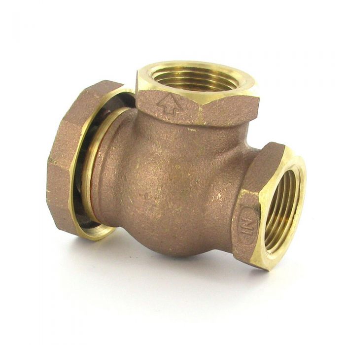
You can shop for this atmospheric vacuum breaker on SprinklerWarehouse.com
Anti-Siphon Valve. A anti-siphon valve is a manual or automatic control valve with a built-in atmospheric vacuum breaker. Like the AVB it must be installed 6 inches (150mm) higher than the highest sprinkler head or drip emitter outlet. If you install any valves, of any type, on the pipes downstream of the anti-siphon valve, the anti-siphon valve will not work! The downstream valve creates “back pressure” on the anti-siphon valve which causes the vent in it to jam in the closed position. If this vent can’t open, the anti-siphon valve will not prevent backflow. It may not be installed in any location where it might ever be submerged under water. (Exception: drain valves for winterizing the system are OK and may be installed after an anti-siphon valve, provided they are configured only to drain the pipe. A properly installed drain valve should not create backpressure on the A/S valve.)
Anti-siphon valves are the most common type of backflow preventer used on residential irrigation systems, primarily because they are simple and inexpensive. Some municipalities do not allow the use of anti-siphon valves, so it is best to check with the water company first. Generally you would install the anti-siphon valves in one or more groups, at the highest point in the area to be irrigated. A mainline pipe is run to the anti-siphon valve location(s) from the water source. Pipes then extend from each anti-siphon valve to the sprinklers or emitter tubes. Because anti-siphon valves must be installed at least 6 inches (150mm) above ground, it is a good idea to put a small planting of shrubs around them to help hide them from view. They are not particularly attractive! Water may come out of the anti-siphon valve periodically, so make sure you install them someplace where a little spilled water will not be a problem. The water will come out of the vent, which is under a cover on the top of the downstream side of the valve (you can see the vent holes under the cover if you turn the valve upside down and look for them.) If water does come out of the anti-siphon it means something is wrong that needs to be fixed. In most cases it means either a stick or rock got into the anti-siphon seal and jammed it open, or the anti-siphon valve was not installed higher than all the sprinkler heads or emitters.
- Never install an anti-siphon valve upstream of any other valve. If you do the anti-siphon valve will not prevent backflow and you have wasted your money buying it. (Exception: drain valves are OK installed after an anti-siphon valve.)
- Never use an anti-siphon valve as a backflow preventer installed on the mainline upstream of other valves. This is a common error that a lot of people make. I have heard employees at home improvement stores recommend installing an anti-siphon valve as a backflow preventer with standard electric globe valves installed after it for each of the sprinkler zones. I have seen many contractors do this also. Both should know better! Don’t you do it!!! It will damage the anti-siphon valve. Plus the anti-siphon valve will not prevent backflow when installed this way. You are no better off than if you didn’t use a backflow preventer at all. (Contractors and suppliers: before you flame me for being wrong, do some research. Don’t embarrass yourself! Most anti-siphon valves have a warning on the box or in the installation instructions about this. Just read the instructions!)
- If you plan to use anti-siphon valves, every one of your sprinkler or drip zone control valves must also be an anti-siphon valve. You can use a ball valve upstream of the anti-siphon valves for an emergency shutoff. However, no valves may be downstream of them. If you are paying attention you will note that essentially this is the same thing I said in #1 and #2 above! Hopefully you’re getting the message by now!
- Anti-siphon valves should never be installed below ground, even if buried in a box.
- You can build an enclosure around the anti-siphon valves to hide them, if they are above ground. However they must be above ground, and the enclosure must allow water to freely drain out of it if the anti-siphon valves leak.
Anti-Siphon Valve Installation Detail
Pressure Vacuum Breaker. A pressure vacuum breaker (PVB) is similar to an atmospheric vacuum breaker except that you only need to install one of them and it is installed on the mainline leading to the control valves. Like the AVB it must also be installed above ground and it must be 6 inches (150mm) higher than the highest sprinkler head or drip emitter controlled by any of the valves. In a sloped yard it would typically need to be installed at the highest point in the yard, with a mainline pipe running up to it from the water source, and then another mainline running back down to the control valves.
A few local authorities require that the PVB be installed within 18 inches (450mm) of the connection to the water source, in which case you can’t use a PVB unless the water source is at the high end of the irrigated area. It may not be installed in any location where it might ever be submerged under water. Some municipalities do not allow the use of PVBs with drip irrigation systems. Some don’t allow the use of a PVB at all, so check with your water provider. A PVB backflow preventer may spit or spill water out from under the cap when backflow occurs, so it should be installed in a location where water spillage would not cause problems.
Warning: If used on a water system where a pump and pressure tank supplies the water (like is used on most rural homes that have a well), the PVB may spit water each time the pump shuts off. This is because the pressure variations caused by the pump and pressure tank system can cause backflow from the irrigation system back into the water system. The likelihood of water spitting, and the amount of water that spits out, both increase with a longer mainline on the irrigation system. So if you have 10 feet (3m) of mainline between the PVB and the farthest valve there is less likely to be water spitting than if you have 500 feet (150m) of mainline pipe. One way to stop, or at least reduce, this water spillage is to install a spring-loaded check valve right after the PVB. The PVB may still spill a little water with the check valve installed, however in most cases it should be much less water.
Pressure Vacuum Breaker Type Backflow Preventer Installation Detail
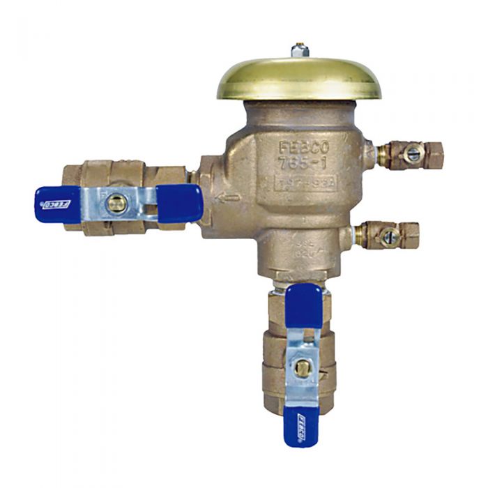
The Febco 765 PVB backflow preventer is available on SprinklerWarehouse.com
Double Check Backflow Preventers. Depending on who you ask, double check backflow preventers may or may not be appropriate for irrigation systems. In many communities they are legal to use, and even recommended by local officials. Other communities do not allow them to be used on irrigation systems. I will attempt to present both sides of the argument.
![]()
Don’t be fooled! A “Dual Check” is NOT the same thing as a “Double Check Backflow Preventer”! They sound very similar, and they are “relatives”, but they are not the same. Dual check backflow preventers are for use with non-toxic materials. A typical use for a dual check is to install it where your house water supply connects to the water district’s pipe. The water in your house is (hopefully!) non-toxic, so a dual check is OK. The water in your irrigation system is not as likely to be non-toxic, so a dual check is NOT OK! How do you recognize which is which when you see them? A Double Check will ALWAYS have two manual valves, one on the inlet and one on the outlet. These manual valves are used as emergency shut-offs and are also necessary to properly test the operation of the backflow preventer. A Double Check will also have test cocks (small outlets sticking out of the side of the backflow preventer) for connecting to test gauges. If it doesn’t have those shut off valves and test cocks it is NOT a Double Check Backflow Preventer! Many communities that allow double check backflow preventers do not allow the use of dual check backflow preventers. Don’t mistakenly buy the wrong thing! For more on dual checks, click here.
First let’s take a look at what a double check is and how it works. A double check backflow preventer is simply two spring-loaded check valves in a row, with a shut-off valve on either end and test cocks to allow the unit to be tested for proper operation. The double check backflow preventer is the only true backflow preventer which does not have a vent to allow air to enter the lines or to allow water to escape when backflow occurs. It relies entirely on the tight seal of the two check valves to prevent backflow. In most places where double check backflow preventers are legal, local officials will allow them to be installed underground in a vault. However, since not all do, you should always check with local officials before installing the unit underground. Double check backflow preventers can be installed lower than the irrigation system and often they are installed in basements in order to protect them from freezing. Regardless of where they are installed they must be readily accessible for maintenance and testing. Even in areas where double check backflow preventers are approved for use they may not be used on any irrigation system where chemicals (fertilizers, pesticides, fungicides, pipe cleaning agents) are injected into the irrigation water.
Double-Check Type Backflow Preventer Installation Detail
![]() For an explanation see my separate article with an in-depth discussion of the pros and cons of double check backflow preventers.
For an explanation see my separate article with an in-depth discussion of the pros and cons of double check backflow preventers.
Dual Check Device. Technically this one is NOT a backflow preventer. It is essentially a stripped down version of the Double Check Backflow Preventer, without the shut-off valves or test cocks. What are they made for then? Just to confuse people? It may seem like it! What they are is a flow control device rather than a backflow preventer. Now I admit there is a thin line of difference between the two. A typical use for a dual check is to install one after a water meter to prevent the meter from running backwards (gee, I wonder why the water company wouldn’t want that to happen?). OK, to set the record straight, I have heard that some authorities do suggest the use of these devices as backflow preventers. In most cases they are requiring them in locations where the general consensus is that no backflow preventer is needed at all. (Most municipalities do not require backflow preventers on water supplies to single family homes, provided water is only used for drinking. The authorities assume that your toilets, washing machines, bathtubs, and dishwashers all have built-in backflow preventers- which pretty much all of them do.) However, some authorities apparently are allowing, and even recommending(!!!), that dual checks be used for irrigation systems, and this is very risky. What if someone wanted to build a nuclear power plant a few blocks from your home, and they decided to build the cheapest model available, one that wasn’t even designed to be used as a power plant? Then to save even more money, they decide to leave out all the test equipment used to confirm that it is not overheating or leaking radiation? Only Homer Simpson could get excited about that! Why would anyone in their right mind use a flow control device that has been stripped of all it’s test equipment as a backflow preventer?
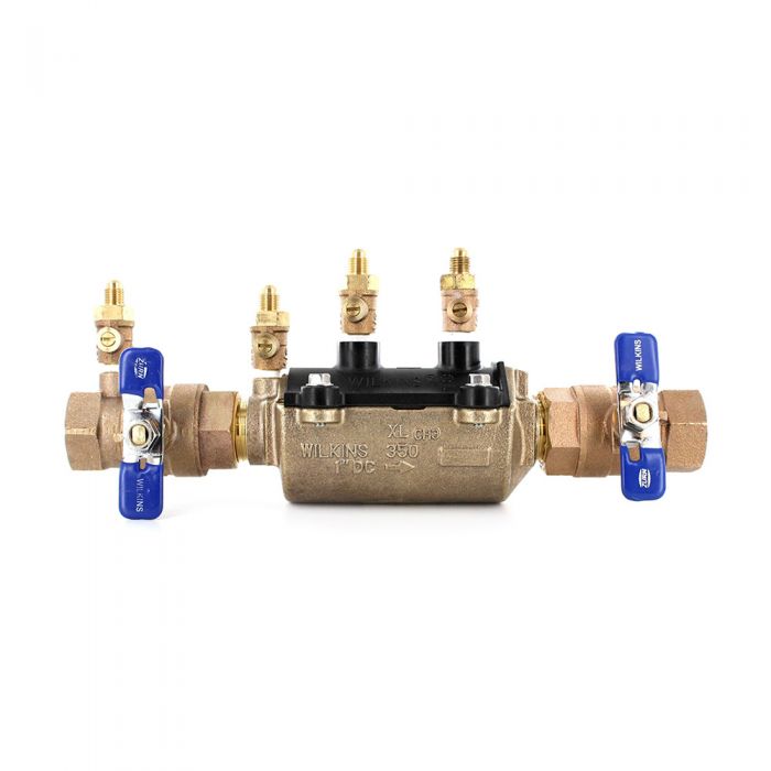
You can shop a wide variety of double check assemblies on SprinklerWarehouse.com.
IMPORTANT!
All backflow preventers must be installed correctly. Follow the instructions that come with the units. Backflow preventers should be checked yearly for proper operation. In areas where it freezes, the backflow preventer should be protected from freezing. See the Irrigation System Winterization tutorial for details.
You can shop for a wide variety of backflow preventers at SprinklerWarehouse.com
This page is linked into several of the tutorials. If you are working through one of the tutorials, please select below to continue the tutorial you are using, or use your browser’s back button.
Return to Drip Guidelines: Back to Drip Irrigation Design Guidelines page.
This article is part of the Sprinkler Design Tutorial Series
<<< Previous Page ||| Tutorial Index ||| Next Page >>>
By using this tutorial you agree to be bound by the conditions and limitations listed on the Terms of Use page.
Sprinkler System Design: Automation, Costs, Contractors, more…
Almost Finished!

Well, if you are working through the Sprinkler Design Tutorial, you’re now pretty much finished with your irrigation design. Here are a few reminders and additional items to consider.
Automatic controllers: For automatic irrigation systems you will need a controller (often called a “timer”) with one “station” for each valve. If you have both lawn and shrub areas you should make sure the controller has 2 or more “programs”. Multiple programs are somewhat like having several “timers” in the same controller. This allows you the flexibility to run the lawn and shrub irrigation on different days. Study the different models and features available on various controllers. Some irrigation controllers and timers allow you to add more zones using irrigation system expansion modules. They range from simple timers to extremely complex computerized units that can monitor all the functions of your entire home! I suggest you take a look at the article on Smart Controllers if you are interested in the latest innovation for saving you time and water.
Isolation valves: It’s a good idea to install a manual shut-off valve at the point where your irrigation system connects to the water supply. I know I already covered this, but not doing it is a big regret that I hear often. An isolation valve allows you to shut down the irrigation for control valve repairs without shutting off the water to your house. You will have to repair a control valve at some time. I recommend using a “ball valve” for the isolation valve, as ball valves are the most reliable and reasonably priced shut-off valves. Most inexpensive “Gate valves” will leak.
Wires for valves: For wires going to the automatic valves use wire made specially to be buried. Most people use a special direct burial cable made for irrigation systems. The cable contains 3, or more, separate, 18 gauge wires. On commercial systems, the standard wire used is “#14-1 AWG-UF” which is a single strand, direct burial type wire. One white color “common” wire goes from the controller to every valve, and one individual “lead” wire of a color other than white goes to each valve from the controller. Be sure to read the Irrigation Installation Tutorial. Also, there is a sketch of typical irrigation system wiring that should help you understand the wiring.
Details: To further help you there is a collection of installation details. These simple sketches will help you figure out how to assemble your irrigation system. These installation detail drawings are normally included as a part of the design drawings for an irrigation system.
Filters: I recommend you install a screen-type water filter upstream of the valves. Drip systems should always have a filter! This helps reduce maintenance problems caused by small bits of sand which are found in almost all water systems. These small sand grains can make the automatic valves malfunction and also clog sprinkler heads over time. A $50.00 filter may seem expensive, but it is a lot cheaper than a $100 valve repair job or replacing a dead lawn. I recommend a “150 mesh screen” in the filter. The filter can be installed underground in a box if you don’t want it visually cluttering up your landscape. On the other hand, it is nice to have it in a more convenient above-ground location for maintenance. Remember, you need to clean the filter screens at least once a year if not more often! For tons of more information on filtration see the Irrigation Water Filtration Tutorial.
Cold Winter Precautions: Unless your irrigation system is in an area where it never freezes you should insulate the backflow preventer and any other above-ground equipment. Backflow preventers are very expensive, you don’t want an unexpected freeze to catch you off-guard. A few years back that happened here in California and thousands of backflow preventers had to be replaced because the water froze in them and they split open! I usually use foam insulation tape to wrap the backflow preventers and above-ground valves, then wrap the insulation with a layer or two of 10mil black plastic tape to protect it. There are also some pretty neat backflow preventer blankets (essentially a big insulated bag), that are made to fit over the backflow preventer like a big coat. They work well, I use them. (I have a small one in my truck that I use to keep cans of soda cool when I’m on the road. It also makes a great pillow!) If the backflow preventer has air vents or a water blow-off outlet it is extremely important that they not be blocked by insulation! There should be instructions that come with your backflow preventer.
Winterization: In areas where freezing weather occurs you need to take precautions to protect your irrigation system from freezing. There is a whole tutorial on winterizing your sprinkler system in areas where it really freezes hard. It covers the various methods used, the advantages and disadvantages of each, and what you will need to install as part of your new sprinkler system for each method.
Pumps: Thinking you might need an alternative water source for your sprinklers such as from a pond or lake? Check out the Irrigation Pumping Systems Tutorial.
How much will it cost?
That’s hard to say. I priced out the materials for the little sample irrigation system at the top of this page at $375.00. That included reasonably good quality sprinkler heads, “funny pipe” type risers, Cl 200 PVC pipe, anti-siphon valves, and a very inexpensive $50.00 controller. That comes to about $0.25 per square foot of irrigated area. You may need to add extra for a better backflow preventer and better controller. I would suggest in most cases that you estimate at $0.25 per square foot plus the controller and backflow preventer cost.
Professional Installers:
Irrigation system installation labor generally costs about 1.5 times the cost of the materials. So a sprinkler system needing $1000 of materials will require around $1500 of labor to install. That would be a total cost of about $2500 including materials and labor if it is professionally installed. Installation costs can vary wildly, be sure to get 3 bids. If any bid is significantly lower than the others it should be regarded as extremely suspicious and it would be wise to use extreme caution before hiring that cheap contractor. Never pay a deposit upfront unless you are willing to risk losing that money. If the contractor needs upfront money insist that he/she deliver materials equal to the deposit value to your house prior to payment. Remember if the contractor needs money upfront to buy supplies that mean the suppliers won’t sell to him on credit. Irrigation suppliers sell to almost everyone on 30-day interest-free credit, so if they don’t trust him/her to pay them that should be a huge warning to you! The irrigation installation business is very easy and cheap to get started in. As a result, it has a huge number of contractors that are under-financed, who don’t have the money to buy the materials needed to do the work they get and then fail. Understand that property laws in the USA allow the supplier who provided the materials to the contractor to place a lien on your home for the value of any materials the contractor buys for your sprinkler system but does not pay for. It does not matter if you paid the contractor already for those materials. The supplier can still make you pay for them again. Fair or not, that is the law. Be smart, protect yourself!!!
Installation
Now you’ll probably want to move on to the Sprinkler System Installation Tutorial. It covers in more detail the various irrigation parts you will use, like sprinkler risers. It also teaches you to “talk sprinklers” (so you can sound like you know more than you do!), helps you make a list of the materials you will need to buy, provides some helpful forms you can print out, explains which tools can make your day or break your back, and a few other tips and tricks! Be sure you read it before you buy anything or start digging!!! (Just when you thought you were finished!)
End of Tutorial
Tutorial Credits:
(As you will note, I’ve enlisted some assistance from my family members!)
Written by Jess Stryker, Landscape Architect, unless noted otherwise
Constructive Criticism:
- Julie Stryker, the love of my life!
- Nathan Stryker, my son.
- Dan Fahndrich of Farwest Gardens, Inc.
- The many tutorial users who have asked questions and pointed out unclear topics.
- And even a few jerks who have kept me (sorta) humble!!!
HTML Coding and page design:
- Jess Stryker & Nathan Stryker
- WordPress
- NoteTab Pro by Eric G.V. Fookes, www.notetab.com
Graphics:
- Jess Stryker
- Nathan Stryker
- Steve Brinkman
Other individual credits are listed on the pages of the tutorial.
This article is part of the Sprinkler Irrigation Design Tutorial
<<< Previous Page ||| Tutorial Index |||
By using this tutorial you agree to be bound by the conditions and limitations listed on the Terms of Use page.
How to Use Pressure and Flow Switches with Irrigation Controls
Almost any major maintenance problem in an irrigation system will cause a unusual pressure level or flow level in your irrigation system. Therefore pressure and/or flow monitoring is a good way to detect problems. Most of the time the response to a abnormal pressure or flow level would be to shut down the system, or possibly to shut down the current valve zone and try another one. Irrigation systems are typically shut down using what is called a master valve. A master valve is a single valve located at the water source that can shut off all the flow of water into the irrigation system. For more details see my article on master valves. On systems with a pump you will probably want to shut off the pump. Sometimes, as with booster pumps, you will need to both shut down the pump and close a master valve.
So what problems might an abnormal pressure or flow indicate? A very low pressure may indicate that perhaps the pump is broken (if you have a pump), an intake screen is clogged, a filter is dirty, a valve failed to open, or a pipe has broken. Abnormally high pressure could be the result of a valve not opening when it should, a dirty filter (if the pressure is measured upstream of the filter rather than downstream) or some obstruction in the pipes. Low flow could indicate a valve failed to open, a filter is dirty, or that a pump isn’t working as it should. High flow could indicate a broken pipe, a broken sprinkler, or a valve that is stuck open. In most cases monitoring either flow or pressure is sufficient as opposed to monitoring both.
How to Monitor Your Irrigation System
There are a number of different ways to detect and respond to abnormal pressure or flows. Following are a few or these. If you would like to suggest other methods, please contact me. I realize this is not an exhaustive list.
The image below shows the Hunter Pro-C Modular 4 Station Indoor Controller which makes automating your irrigation easy and user-friendly.

If you need to irrigate a larger property, or require more specialty zones, check out the Hunter PCC 12 Station Indoor Controller.
Use a Smart Irrigation Controller that has a Sensor Input and Response Feature:
This is probably the easiest way to add pressure detection and response. It is also what I consider to be the preferred method, as it is reliable and gives you the most control. Some high-end irrigation controllers can use an electronic sensor hooked up to the mainline pipe to monitor the water in the irrigation system. Some of these controllers use flow sensors, some use pressure sensors, some can use both types. These controllers with advanced features are typically sold as Smart Controllers and are expensive compared to ones typically found on a residential irrigation system. Prices for these controllers typically start around $300.00 and go up into the thousands for ones that handle dozens of stations. Some controllers can increase the number of zones with an irrigation controller expansion module. But then you get a lot more with them too. They are sold through professional irrigation supply stores, both online and locally.
WARNING: Be sure the controller will do exactly what you want BEFORE you purchase it! Not all controllers marketed as “Smart Controllers” have these sensor input features, many only work with specific types or even models of sensors, and some controllers may not provide the response options you want or need. You need to research the controller carefully. Don’t rely on a simple check list of features! “Sensor input” can mean almost anything, you need details! I have seen controller feature lists where the unit sounded fantastic and ultra flexible, only to discover after closer examination that the actual response features don’t do what I need or want. Read the actual owner’s manual (most controller manufacturer’s have them available on their websites) to see what the true capability of the controller is. Read the sections of the manual on how to hook up the sensor, then there will also be a separate section on how to program the sensor you should look through. Some controllers allow for time delayed responses, some don’t. If you have a pump you will almost always need a time delay feature to bypass the sensor when the pump is starting up. Even those controllers that do allow you to add delay times may not allow as much or little time as you need. It is critical that you do as much research as possible before you go to the expense and effort of purchasing, installing and programming the controller.
For example, I have a Rainmaster Eagle Smart Controller on my own irrigation system, as well as using it on the majority of the commercial systems I design. This particular Smart Controller has flow sensing capabilities, but it does not have built-in pressure sensing capability. It does have a delayed response allowing delays of 1-6 minutes, but only in one minute intervals. It will also allow the use of one additional simple on/off type sensor (most controllers have a circuit for this type of very simple sensors. A simple rain switch is an example of this type of sensor.) It has an audible “chirp” alarm that alerts you that a sensor response has been activated. While this particular controller meets my needs, it certainly will not meet everyone’s. Almost every major irrigation company makes a Smart Controller, and each has different features and capabilities. Be sure you are using up-to-date resources when checking out models. Smart Controller models are introduced each year, and often the capabilities of existing models change from year to year, so it is hard to keep up with them.
When using a controller with a pressure and/or flow sensor you start by installing the actual sensor on the mainline pipe. The method varies with the brand and model of sensor, most are pretty easily installed. The sensor is wired to a special terminal on the irrigation controller. Typically the wire used must be a special shielded communications cable, rather than standard irrigation valve wire. Consider installing communications cable in PVC conduit to protect it, as it is very sensitive to even the smallest nicks from shovels, animals digging it up, or rodents chewing on it. Most pressure sensors work by sending a reading of the current pressure to the controller every few seconds. A typical flow sensor has a small paddle that turns as the water flows through the pipe. Flow sensors normally send a signal based on the amount of flow, for example they might send a signal each time 5 gallons of water has flowed past the sensor. The controller then interprets that data from the sensor and responds. In most cases you will pre-decide what the response will be when you set up the controller. For example; if you have a system with a pump, you could program the controller to shut down the irrigation system if the pressure was below 10 PSI for more then 2 minutes during the set irrigation period. The 2 minute qualifier (delay) for shut down would allow the pump time to pressurize the system during start up and also avoid “false alarms” caused by brief dips in pressure.
Using a Simple Pressure Switch with a Pump Operated System:
This method is for those with pumps. What I am describing here is for emergency shut off only. I’m assuming you already have something set up to turn on or off the pump during normal irrigation operation. That might be a standard pressure tank with a pressure switch to control it. Or you may be using the pump start feature on the irrigation controller to actually start and stop the pump using a 120v relay. The new pressure switch we are talking installing in this case is used only to detect pressures that indicate a problem and turn off the pump. So if all is hooked up properly, in the event of blockage or no water going into the irrigation system the pressure will drop and the new pressure switch will shut the pump off.
This method requires that your irrigation system is leak free and can hold pressure for days between irrigations. If the system is not leak free see #4 below.
1. Make sure you have a really good quality spring-loaded check valve on the irrigation mainline pipe. The check valve goes someplace after the pump, but before the pressure switch. A good quality check valve is needed to keep the water from leaking backwards out of the system through the pump. Typically the self-priming feature of the pump is not good enough by itself to do this, you need a separate check valve.
2. You will need to use a pressure switch that works backwards from normal ones used for household water systems, since you want the switch to shut off the pump at low pressure (standard switches used on household water systems turn on the pump at low pressure.) Some switches can be wired to work either way, others can’t. Keep in mind that the low end on many common pressure switches in around 25-30 PSI. That might be a bit higher than you want for a low end shut off, especially if your system will be operating at less than 45 PSI. You don’t want accidental “false” shut offs since the only way to get the system back on will be to manually start the pump and hold it on until the pressure is back above the shut-off level.
3. There a problem to be dealt with. The problem is that valves close slowly, taking as much as a minute or two to close after the controller tells them to. At the end of the last irrigation cycle a typical controller closes the last valve and immediately shuts off the pump. But it takes the valve several seconds up to a minute or two to actually close. During this closing period the system will depressurize. With no pressure in the system the pump will not restart for the next irrigation cycle, because the low pressure shut-off switch is detecting low pressure and shutting off the power to the pump. There are two ways to deal with this.
A. You can fool the controller into keeping the pump running after the last valve circuit has finished watering. Your controller needs to have the capacity for one extra valve on it to do this, so if you have 10 valves you will need a controller with 11 stations. The last station on your controller needs to not have a valve attached to it. Program 1 minute of time on that last station. Now the controller thinks it is operating one last valve, so it keeps the pump running. That will keep the system pressurized while the final valve closes. If one minute is not enough time for the final valve to close then add another minute of run time to that last empty station.
B. Some controllers have a built in delay feature that keeps the pump running after the last valve closes. This feature keeps the pump start circuit energized, which keeps the pump running for a minute or two after the last valve is signaled to close. This gives the valve time to close before the pump is shut off. Some less expensive controllers have this feature. But typically only high-end controllers have this feature, so this method isn’t very practical. If you are going to buy an expensive controller you might as well forget about using a pressure switch and use a Smart Controller and a sensor to shut the system down, as described in the first section of this article.
4. Often a small leak will cause the system to depressurize between irrigation runs. This can be a major problem. The pump will not start if the pressure is low, the low pressure switch is going to shut off the power to it.
If the leak is very small you can install a pressure tank, just like on a typical house water system. Assuming a small leak, the tank keeps the system pressurized. But that only works with a very small leak and it can take a huge pressure tank to supply enough water to keep the system pressurized. If your system has a larger leak you will need to find and repair the leak. If you can’t get the system leak free, you will need to take a different approach, as described below.
You can use a timer to over-ride the low pressure switch, and allow the system to start even with no pressure. You will need a “Time Delay Relay”. The time delay relay needs to be the type that allows the power to flow when energized, then shuts it off after a minute or two of delay. It needs to have an automatic reset. You then install the relay on a bypass wire around the low pressure switch. That way the pump can start even when the pressure switch is “off” due to low pressure. You will need to work with someone knowledgeable when ordering the time delay relay to be sure you get the correct relay, as they make many different kinds.
Using a Pump Controller with a Sensor:
This is essentially the same method as the Smart Controller method I described earlier. Only the “smarts” are in the pump controller rather than in the irrigation controller. Some of the newer digital pump controllers (don’t get confused here, we’re talking about a separate pump controller, not the sprinkler controller) are programmable, they are simply a small computer that operates a relay that starts and stops the pump. You hook them up to a pressure sensor, also to the irrigation controller, and to any other sensor you want (wind, rain, temperature, light, flow, you name it.) Then you can program them to do just about anything using that information input. They can turn off the pump if a low pressure occurs for more than x number of seconds, turn off the pump if a high pressure occurs for x number of seconds, turn on the pump at a given time of day, etc. Pretty much any input you want can cause the pump to turn on or off. The capability depends on the brand and model of the pump controller. The downside is it takes electronics know-how to set the thing up and someone tech savvy to program it. Typically you hook up a laptop to the pump controller to program in the logic, then once it is programmed it runs by itself. The laptop just gives you an interface that is easier to work with. I really can’t give you much more details beyond that, this type of pump control is beyond my expertise, I just have seen pump system experts use them to do amazing things.
How to Estimate Water Useage Required for an Irrigation System
The amount of water needed for irrigation depends on many different factors. A reasonably accurate estimate of the amount of irrigation water needed can be made using Eto data for your actual zip code. “Eto” is the amount of water needed for irrigation, based on scientific research. You can find the historic Eto for any zip code in the USA at the website http://www.rainmaster.com/historicET.aspx courtesy of the Rainmaster irrigation controller company, which makes very good “Smart” irrigation controllers. I use one of their Eagle model controllers in my own home. (Rainmaster gets a plug from me as well as a big “thank you” for providing the ETo look-up service online.) Unfortunately, the Eto value only tells you how many inches per day are needed, which for most folks is a meaningless value. It makes more sense if you think about rainfall which is often also measured in inches. If you find you need 0.20 inches of irrigation, then 0.20 inches of rainfall would provide the required water. But most people in the USA want a value in gallons, which requires you to provide a little more information about your yard. Then you plug the values into a simple formula and do a little multiplication and division on any calculator.
A WiFi-ready controller can help automate watering your lawn. The Rain Bird ESP-Me 4 Station WiFi Ready Indoor Controller is pictured below:

Formula to calculate the gallons of irrigation water needed per day:
(Eto x PF x SF x 0.62 ) / IE = Gallons of Water per day
Values for the formula:
Eto: Get this from http://www.rainmaster.com/historicET.aspx . Enter your zip code or a nearby zip code, and the website will give you the average daily ET value for each month of the year. Use the highest value or the “suggested reference value”. Usually they are the same thing.
PF: This is the plant factor. Different plants need different amounts of water. Use a value of 1.0 for the lawn. For water-loving shrubs use .80, for average water use shrubs use 0.5, for low water use shrubs use 0.3.
SF: This is the area to be irrigated in square feet. So for a 30-foot x 50-foot lawn, you would use 1500.
0.62: A constant value used for conversion.
IE: Irrigation efficiency. Some irrigation water never gets used by the plant, this value compensates for that. I suggest using 0.75 as the value for this. Very well designed sprinkler systems with little run-off that using efficient sprinklers can have efficiencies of 80% (use 0.80). Drip irrigation systems typically have efficiencies of 90% (use 0.90).
Example:
A 1500 square foot grass lawn in zip code 85232 (Central Arizona)
Start by looking up the Eto for zip code 85232 at the Rainmaster website, which displays a suggested reference value of 0.3 inches per day using June, the driest month of the year in that area.
Now rewrite the formula inserting your values into it:
0.3 (Eto value) x 1.0 (grass value) x 1500 (sq ft) x 0.62 ÷ 0.75 (efficency factor) = gallons of water per day
Now do the math, just punch the values into a calculator and get your answer:
0.3 x 1.0 x 1500 x 0.62 ÷ 0.75 = 372 gallons per day
We could figure out the average daily water use for other months of the year also. Just use the same formula but insert the Eto value from the Rainmaster website for the month you want to get a valve for.
Remember this calculation just gives you an estimated value. There are many other factors that could make this value higher or lower. When planning for how much water a system that has not yet been designed or installed will use, it would be very wise to allow for error by adding 10% or more to the daily water use needed. It is generally better to have too much water than to have too little! Play it safe!
A common related question is “how much water pressure will my irrigation system need?” The answer depends on a lot of factors, but as a rule of thumb, I would suggest 50 PSI of water pressure as a good starting point for sprinklers, 45 PSI for drip systems. If you have a large yard and want to put the sprinklers farther than 30 feet apart you will need more pressure. For example, if you want your sprinklers 45 feet apart you will probably need 65 PSI of water pressure. To get real value you will need to create an actual sprinkler system design. See the Landscape Sprinkler Irrigation System Design Tutorial.
Never buy a pump, sprinklers, or any other materials before your sprinkler design is completed!
Selecting A Pump Using Pump Curves
This part of the Pump Tutorial Series. The 1st page is at Pumps: Selecting-a pump step-by-step.
Selecting a Pump Model, Horsepower, & Impeller Size
The best and easiest way: contact a pump dealer and give him/her the pressure you need (feet head or PSI), and the volume (GPM) you want to pump, they can figure out which pump you need. This is the best way to select a pump, as the dealers know their pump lines much better than you. They may suggest a pump you don’t even know about.
The Do-It-Yourself way
The rest of this page will take you through the process of selecting the right pump model for your irrigation system. It is assumed you read the previous pages and already have decided what type of pump you need and you know, or will soon know the pressure and flow your pump will need to produce.
Generally it is not a good idea to buy an “off-the-shelf” boxed pump at a store for use on an irrigation system. Most of those pumps do not provide sufficient performance information on the packaging for you to be able to tell if the pump is sufficient for your system. Off-the-shelf pumps are fine for fountains, draining a pool, running a sprinkler on the end of a hose, or other uses that don’t require precision. The wasted power used by the wrong size pump on an irrigation system can easily cost you far more than the savings you get from buying a discount pump. If you guess wrong and the pump isn’t big enough, you will become one of those poor people trying to unload a brand new pump for half what you paid for it at an online auction!
Pump Curves
A pump curve is a simple graph which shows the performance characteristics of a particular pump. Some pump manufacturers use charts rather than curves, the idea is the same, curves just tend to be more flexible to use. Pump curves are created by the pump manufacturer based on test results of the various pump models the manufacturer produces. The pump manufacturer should be able to provide you with performance curves for the pumps you are considering. Remember, there is always an inverse relationship between pressure and flow. Higher pressures mean lower flows. Lower pressures result in higher flows. Here’s a sample pump curve for study:
OK, that was a big help, right? No? OK, so how in the world do you use the thing? Here’s a step-by-step guide to the pump curve above. The pump curve above is for a centrifugal type pump, but the curves for other pump types are used the same way.
Each pump curve typically reflects a single model of pump made by the manufacturer. At the top right of the chart you will notice it gives the pump speed, in the chart above this is 3500 RPM. It is said that higher speed pumps wear out faster, but to be honest, we have never noticed a difference. We pretty much ignore the speed and try to select the pump with the best performance for our needs. There are other opinions on this, so be aware it is one of those areas of disagreement in the industry.
For each model there are two variables which effect the pump performance. The first is the horsepower of the motor attached to the pump. Remember, what we commonly refer to as a pump is actually combination of two items: a pump and motor. The pump is the part that moves the water, the motor is the part that moves the pump! Most pumps can be attached to several different sizes of motor. Bigger motors mean more volume and pressure.
The second variable is the size of the impeller. As you remember the impeller spins inside the case and this is what moves the water. Larger impellers move the water faster creating more centrifugal force. This results in higher pressures.
Look at the left side of the curve and you will see a label HEAD – FT and numbers starting with 0 and increasing as you move up the chart. This is the pressure that the pump is capable of producing, measured in feet of head (not PSI!) The bottom of the curve is labeled US GPM. This is the flow that the pump produces.
Finding the proper pump is just a matter of selecting a model and size that will produce both the head and GPM that you need. To do this you select the horsepower and impeller size that will give you the desired performance.
Using the Curves
Notice the red color curved lines (the top one in the pump curve above is labeled “6.00 IN. DIA.”). These represent the various impeller sizes. Now notice the green color straight lines which intersect the impeller curves (the top one in the pump curve above is labeled 5 HP). These lines represent the motor horsepower ratings available for this pump. Together the impeller curves and horsepower lines represent the best performance the pump is capable of if that horsepower or impeller size is selected. Some pump curves do not have horsepower lines, and some pump curves combine the horsepower and impeller lines into one single line. This is usually because the pump only is available with one motor, so you don’t get to select the horsepower. The pump may also only come with one size of impeller, so you will only see a single line on the entire pump curve!
To use the curves you select the pressure you want on the left and then move horizontally across the chart to the vertical line that corresponds with the flow (GPM) that you want. You then select an impeller size curve and horsepower line that are above this point to determine the impeller size and horsepower you will need for your pump.
The following examples are based on the pump curve above.
Example #1: You want a pump that produces 125 feet of head while pumping 100 GPM. Start at 125 ft. hd. on the left of the pump curve. Now move straight across the curve to the right until you reach the line that goes down to 100 GPM on the bottom of the curve. From the point where the two lines intersect move up the chart to see what horsepower pump will be needed. In this case a 5 HP will be needed as the next horsepower line above our intersection point is the 5 HP line. Likewise, the impeller curve must also be higher in the chart than our line intersection, so a 6.00 IN. DIA. impeller will work.
Example #2: For 70 ft. hd. and 80 GPM. Make a mark at the point where the horizontal 70 ft. hd. line intersects the vertical 80 GPM line. This point is just above the 2 HP line, so a 2 HP pump will NOT work. We will need to use the 3 HP motor. The next higher impeller size is 5.00 IN. DIA. so we could use that impeller (but we might not, see “custom impellers “below).
Custom impellers
If you order it, they will build it! Pumps can be ordered with custom impeller sizes. In fact, this is the most common way pumps are sold. This often does not cost much more than a “off the rack “pump, but it does take a little longer to get the pump since they need to custom build it! Almost all of the pumps pros use have custom impeller sizes. To determine the custom impeller size you simply draw a new impeller curve through your ft. hd./GPM intersection point so that the curve is parallel to the other impeller curves. Then you determine the impeller size by comparing your new curve with the other impeller curves.
Example: If your new curve is midway between the 5.00 inch curve and the 6.00 inch curve then you would need a 5.50 inch impeller!
The good news is that you don’t really need to do this, when you order the pump the manufacturer will ask you what your feet head and GPM requirements are and they will calculate the best impeller size for you! Then they will grind one down to the correct size for you. Now that has to make you feel pretty important. Plus, you get bragging rights; “I had this pump custom built for my yard, it’s one of a kind!” The negative side of this is you generally can’t return a custom built pump. So get that pressure and flow requirement right.
Pump Efficiency
On many pump curves you will see an additional set of ellipses labeled “efficiency ” or you may see percentages labeled on the other curves. For clarity I left these off of the example pump curve. These ellipses indicate the efficiency of the pump. To use them you simply look for the smallest ellipse that your line intersection point is inside. This is the efficiency at which the pump will operate. The higher the efficiency the better! A high efficiency pump uses less energy ($) to operate than a low efficiency pump. If possible, it is best to avoid any pump that has an efficiency of 55% or less. 55% efficiency is the industry standard used to estimate the performance of a pump when the actual efficiency is unknown.
Read the Manual
All pumps have oddities and special and unique requirements. Before installing a new pump always read the Owner’s Manual.
Go to the next page –> Pump Controls
Designing a Irrigation System to Use a Existing Pump
This page is part of the Pump Tutorial Series. The 1st page is at Pumps: Selecting-a pump step-by-step.
If you have an existing pump and want to design an irrigation system that uses it as the water source, the Irrigation Design Tutorial will take you through the process. Rather than rewrite the entire tutorial on how to design and irrigation system we’ll just send you over to the one that is already written! It will show you exactly how to test your existing pump to determine the flow and pressure output. Then it will take you through the process of designing an irrigation system to use your existing pump, including some tips and tricks that are just for use in designing irrigation systems that use pumps!
Continue reading Designing a Irrigation System to Use a Existing Pump
Sprinkler System Installation Tutorial
This landscape sprinkler and drip/trickle installation tutorial will take you step-by-step through the process of constructing (or assembling) your new sprinkler irrigation system. During the process you will learn a lot of tricks as well as how to “speak irrigation talk” which can be helpful when you are working with others in the industry. Why speak the lingo? Well for example when buying your materials it is a quicker if you can say “I need a three-quarter by three-quarter by half slip-slip-thread tee” rather than “I need a outlet thingy to go on my pipe to connect a sprinkler to it.” That first description may seem confusing to you now, but you will know exactly what it means very soon. We’ll also give you some checklists and forms you can use to make this all easier and save a lot of trips to the store to pick up stuff you forgot.
Quick reminder, if you haven’t designed your sprinkler system yet you need to do that before you continue. See the Sprinkler System Design Tutorial.
Sprinkler System Installation Tutorial
Table of Contents
- Creating Your Shopping List of Materials (aka a “Take-Off”.) Creating a complete and accurate “take-off” is the first step to install your irrigation system. This section tells you how to do it right!
- Take-off Form. A easy to use fill-in-the-blank form that lists the most common materials used in the installation of drip irrigation and sprinkler systems.
- Fittings take-off Form. A ready to use form that lists the most common PVC fittings used when installing a sprinkler or drip irrigation system.
- Checklist. A checklist of items commonly needed to install a sprinkler or drip irrigation system. Review it before heading to the store!
- Understanding Fittings. A complete guide to common PVC fittings, including the correct terminology to use when describing them to others. Includes sketches of each fitting.
- Sprinkler Risers. The sprinkler riser plays a large part in determining how often you will need to repair broken sprinklers!
- Anti-Siphon Valves. The most common valve type for residential irrigation systems.
- Globe-Valve Installation. The most common valve type used for commercial irrigation systems.
- Miscellaneous Installation Details. Lots of sketches showing how to fit it all together! Don’t guess how to put it together, save tons of time using these!
- Irrigation Installation Tools. Tools and tips for using them that make the job easier.
OK, time to get outside and start kicking up dirt! - Layout Your Irrigation System. Mock up the system. Make sure you have everything, check for design errors before you start digging!
- How to Make a Leak Free Threaded Pipe Connection. How to connect threaded pipe ends so they won’t leak.
- Safety First! A list of safety precautions and tips to make the job more pleasant.
- Connect to Water Supply. How to tap into the water supply.
- Install Underground Piping. Tips for installing the piping and wire.
- Backfill & Flush. Proper flushing is critical to your system’s survival.
- Install the Sprinklers on the Risers. Install them the right way and it will massively reduce the need for future repairs.
That’s a lot of pages of information but a lot of it is checklists and diagrams that you will just skim over quickly, so don’t get discouraged! Better to spend 15 minutes reading the tips here than an hour installing it wrong, and two more hours removing and redoing it!

Designing A New Irrigation System to Use an Existing Pump
If you already have a existing pump installed you should design your irrigation system to work with the existing pump, if possible. The Irrigation Design Tutorial will take you through the process of determining how much flow and pressure your existing pump can produce (the pump capacity), then you can design the irrigation system to match those parameters.
First:
There is a correct way to measure the capacity of your existing pump and there are lots of wrong ways to do it. If you use one of the wrong ways, (and they are suggested all over the Internet) really bad things are potentially going to happen. One is that the irrigation system you just spent a pile of money on may not work, it may just dribble water from the sprinklers. The next is your pump may burn out. Third is your pump may surge each time it starts and eventually that will cause massive damage to the irrigation system pipes and valves. You don’t want any of these things to happen! So you need to get this measurement of your pumps capacity right because your whole design depends on it being correct. Remember, “garbage in, garbage out.”
Start by reading through the Measure Your Water Pressure – Country Bumpkin Water page of the Irrigation Design Tutorial to get an idea of what needs to be done. It will guide you through the process of evaluating your existing pump to assure it is sufficient for your proposed irrigation project.
Warning: Designing an irrigation system that uses a pump requires several steps/considerations that are not necessary if you have a city water supply. If you design the sprinkler system wrong it can wreck your pump so it is best to use a sprinkler design tutorial that is written for people using pumps! There is a lot of incorrect information online on irrigation design with pumps, including some on major irrigation company websites.
Please, read the Country Bumpkin page so you know the right way to do it! Yes, we know that’s a silly name for the page, we wanted it to grab your attention because the information is so important.

Second:
It won’t hurt to learn a bit more about pumps before you go on to the irrigation design. You might want to check out the following articles that provide background information on pumps:
Types of Water Pumps
Basic Pump Hydraulics.
Third:
After looking over those pages just hop over to the Irrigation Design Tutorial for step-by-step instructions on how to design your irrigation when using a pump.
Related how-to pump articles:
Selecting A Pump For A New Irrigation System.
How to Select a New Pump for an Existing Irrigation System.
How to Design a New Irrigation System to Use wit an Existing Pump.
How to Improve the Performance of an Existing Pump.
How to Select a Pump for a Rainbarrel.
How to Design A Landscape Sprinkler Irrigation System like a Pro!
Whether you’re a professional landscaper or want to irrigate your own yard, this free Landscape Sprinkler System Design Tutorial is designed to take you step-by-step through the process of creating a professional-quality sprinkler irrigation plan, layout, or drawing.
There are lots of Sprinkler Design Guides, Why This one?
- This tutorial works with ALL sprinkler products and does not base your design on the use of a single manufacturer or store’s products. Most tutorials will force you into using specific products on your plan. Sometimes they are good products, sometimes not. Bonus: This tutorial will teach you how to spot the really bad irrigation products.
- This tutorial assumes you know nothing about irrigation and breaks it all down for you (but the beginner stuff is easily skimmed over for those more experienced.)
- This tutorial is multi-level. Many of the topics start with a outline of the topic, then expand on that outline in detail for those who need more explanation. Finally some subjects then move on to cover special situations or layout that are not “typical” for those who need that additional insight. So while some tutorial pages are long, you may not need to actually read a lot of it. Unless you are a future irrigation professional and interested in learning all about irrigation, which leads us to the next point…
- This guide is complete. It is used by colleges to teach irrigation design courses, and we encourage that use. However, it is written using 6th grade level English, so don’t panic. If you were ever a broke college student you can probably appreciate the idea of a free online textbook! Speaking of free…
- This tutorial is free. Yes there are some ads, along with a few “tips” they pay the cost of keeping it online. The ads on this site are low key. No flashing ads, no pop-ups (except the “we use cookies” pop-up notice that is required by law.)
- If you have a well and/or pump this is one of the only sprinkler system design guides available anywhere (including those $$$ books for sale at stores) that will show you how to correctly design your system so that it will not destroy your pump by making it cycle or run dry.
- Thousands of people have used this tutorial to create their irrigation systems drawings. This tutorial has been online a while, the first version was written back in 1995. You may find an error or two in it (especially in the grammar, it was written by an irrigation expert, not an English major) but most of the technical errors have been found and corrected long ago. Tons of feedback have resulted in rewrites of the parts that were not clear. The advantage of being online is that the tutorial does get constantly updated to incorporate new products, ideas, and methods.
- This tutorial was written by a professional irrigation designer and licensed landscape architect who has over 35 years experience designing irrigation for everything from small tract yards to golf courses. More on the author at the bottom of this page.
Warning: There are lots of online tutorials and this one may not be your choice and that’s fine. However there are a number of design guides around, both online and in stores, that use outdated design methods. Please watch out for these major design errors that may lead to very expensive repairs:
- Beware of measuring flow with a bucket or gauge. The “GPM” value for your new sprinkler system should be based on the size of the existing water supply pipe running to your house. Some do-it-yourself sprinkler system guides have you measure water flow by turning on an existing faucet and timing how long it takes to fill a bucket. Some also suggest using a special gauge that measures the flow. Regardless of how you measure the flow, we now know that just measuring the flow from a faucet results in major errors that can result in your using a irrigation system flow that is way too high for your house’s plumbing to handle. When you turn on a faucet the water from it will often flow out at a rate that is way higher than what is safe for the pipe’s in your house. While running water for a few minutes at this flow to fill a bucket is relatively harmless, running a sprinkler system at that flow on a regular basis is not. This unsafe high flow results in “water hammer” and “scrubbing” damage to the pipes, two very expensive problems that can destroy the pipes in your house. We are talking thousands of dollars to re-pipe your house! The key here is that when determining the water supply volume the pipe size must be a factor considered.
- Sprinklers should have almost 100% overlap. If a sprinkler layout guide shows you coverage arcs that are not going almost all the way from one sprinkler to the next it is based on the old way of doing things back before we had low-flow sprinklers to conserve water. Almost all experts now agree that there should be near 100% overlap of sprinklers. Back in the old days we just told people with dry spots to run the sprinklers longer. That over-watered 90% of the lawn but it greened up the dry spots. We now know it wastes water and even worse, over-watering causes lots of landscape diseases!
All the information you need to create a sprinkler system design for your lawn, shrubs or garden is in this landscape sprinkler design manual. Illustrations, charts and spreadsheets will help explain and simplify the sprinkler irrigation design process. You will learn about lawn sprinklers, shrub sprinklers, and how to select a quality sprinkler head. Automatic and manual valves, controllers/timers, and the basic hydraulics that apply to watering systems are also covered.
Most of the pages of the tutorial are written as stand-alone articles, so that they will be useful to those who do a search for specific information. For this reason there is a small amount of repetitive material throughout the tutorial.
Continue reading How to Design A Landscape Sprinkler Irrigation System like a Pro!
Backfill Trenches and Flush Pipes
This page leads you step-by-step through the backfill and flush process. Quick summary:
- Backfill trenches 1/2 full. Do NOT install sprinklers yet.
- Flush entire system for 5 minutes with all valves open.
- Cap all sprinkler risers leaving only one open and flush for 2 minutes. Cap the riser after flushing and repeat with the next riser, flushing the remaining risers for 1 minute each. Repeat for each riser until all are flushed.
- Finish backfilling trenches, don’t backfill around the risers.
Selecting A Pump For An Existing Irrigation System
This page is part of the Pump Tutorial Series. The 1st page is at Pumps: Selecting-a pump step-by-step.
If you have an irrigation system that currently has a pump on it, and everything has worked good right up to the point the existing pump died, then your best bet is to replace the pump with the exact same model as the old one. This is a much, much easier process than trying to find a different make or model of pump. However if the old pump wasn’t really getting the job done, or isn’t available anymore, this is a good time to reevaluate your pump needs. Perhaps there is a better pump out there for your system. This tutorial will teach you how to do that.
Continue reading Selecting A Pump For An Existing Irrigation System
Pumps: How to Select the Right Pump
This tutorial will take you step-by-step through the process of selecting the right pump for your irrigation system. (Not looking for an irrigation pump? Most of the pump principles presented here apply to any pump use, not just irrigation.) Most irrigation pump situations you may encounter we will cover, but you will need to do a bit of reading. That is the do-it-yourself way. If you don’t want to take the time to educate yourself you should stop here, and hire a local pump professional to come out to your property, do the research necessary, and recommend a pump for you. There is no shame in having a pro help you if the job is over your head or just too time consuming!
NOTE: There is no “easy way” to select a pump. There are two things you must absolutely know in order to select the right pump: the irrigation system operating pressure and the system flow rate. If anyone tries to tell you what pump you need without establishing what your needed flow (GPM or l/m) and pressure (PSI or bars) are they are just guessing. That’s like determining how many marbles it takes to fill a jar. Without knowing how big the jar is, and how big the marbles are, all you can do is take a wild guess!
Now first let’s start by getting you around the huge beginner’s mistakes.
Selecting A Pump For A New Irrigation System
This page is part of the Pump Tutorial Series. The 1st page is at Pumps: Selecting-a pump step-by-step.
Here’s the basic procedure to follow if you’re trying to find the right pump horsepower and model for a new irrigation system. You’ll probably want to refer back to this list as you learn more.
Continue reading Selecting A Pump For A New Irrigation System
Types of Water Pumps for Irrigation Systems
This part of the Pump Tutorial Series. The 1st page is at Pumps: Selecting-a pump step-by-step.
There are numerous types of pumps designed for various purposes. Pumps commonly used for irrigation fall into two broad categories: Displacement Pumps and Centrifugal Pumps. Within those categories there are sub-categories that further define the type of pump. This tutorial will focus on those types of pumps most often used for irrigation.
Continue reading Types of Water Pumps for Irrigation Systems
Compression Tees and Couplings
A compression coupling or tee is a special fitting designed for joining existing metal and PVC pipes or tubes. They are sometimes sold as “pipe repair couplings”. They are primarily used for underground connections. Other types of compression fittings, such as threaded adapters, are also available for situations where something other than a coupling or tee is needed. Compression couplings are primarily used for pipe repairs, compression tees are used to tap a new pipe/tube into an existing one. A compression fitting may be constructed of PVC or metal. PVC should only be used for connections that will be hidden from sunlight, like underground or in a box.
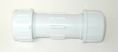
Stake Out Your Sprinkler System
The first step in physically installing your sprinkler system is to layout, or “stake”, your new irrigation system on the ground. Start by marking each of the sprinkler head locations in the irrigated area, using your sprinkler system plan as a guide. (Don’t have a plan? Stop here. Don’t make trouble for yourself. You NEED a plan!)
Place a stake, a flag (they sell flags for this purpose at irrigation supply outlets), a long nail with a ribbon tied to it, or whatever, at the location of each sprinkler head. (At this point I suggest you NOT use paint as a sprinkler location marker, you may need to make adjustments and paint makes that difficult.) Now carefully double check the distances between each of the sprinkler heads. You don’t want to find out that the sprinklers are in the wrong place after they are buried in the ground! Measure the distance from each sprinkler head to the next head in each direction. If your system is properly designed there should be at least 2 other sprinklers (usually 3) about the same distance away. Make sure that none of these distances are more than the maximum spacing allowed for that sprinkler head model. (See the Sprinkler Design Tutorial for more information on maximum sprinkler spacings.)
Rule of thumb spacing guidelines:
- If the distance between spray type sprinklers is more than 18′ there’s a problem.
- If the distance between rotary nozzle type sprinklers is more than 35′ there’s a problem.
- If the distance between rotor type sprinklers is more than 35′ there’s a problem.
- If the distance between any 3 adjacent heads varies more than 20% there is a problem.
- If you don’t know what spray, rotary nozzle, and rotor type sprinklers are read the article on Types of Sprinklers.
The spacings shown above are maximums! The best spacing is probably less than these distances! Remember, the water from one sprinkler should spray all the way to the adjacent sprinkler. Sprinklers are designed to require 100% overlap. You will have dry spots without that required overlap. (This is not greed on the sprinkler manufacturer’s part, there is a scientific, mathematical reason for this overlap. See the article on Sprinkler Spacing for details. )
If the sprinklers are too far apart you will need to adjust the sprinkler locations, another solution is to adjust the perimeter of the area to be watered to make it smaller, or redesign the system. Never stretch the spacings between sprinkler heads beyond the maximums, you will get very noticeable dry spots! Remember that it is easier and cheaper to redesign everything at this point than it will be to fix problems later! Adding more sprinkler heads to a system later in an attempt to get rid of dry spots generally does not work out well, is a lot of work, much more expensive, and almost always just creates new problems. (Right now it may seem like you need to rush to get this sprinkler system in the ground, but waiting a few weeks to fix the problems is nothing compared to the grief of living for years with a horrible sprinkler system that doesn’t work. Many, many regretful owners of bad sprinkler system have told me that this is advice they wish they had heeded.)
Now you need to mark the pipe locations on the ground. You can use chalk, white paint, or just drag a shovel over the ground to mark where the trenches will be.
For do-it yourselfers I recommend that you mock-up the pipes at this point. Lay the pipes on the ground (don’t cut it yet, just use full lengths to get a feel for the layout) and then lay the fittings next to the pipe at the locations of the sprinkler heads, drain valves, junctions (tees), and bends (ells.) This will help you visualize how the whole thing will fit together and will identify any missing fittings you need to buy. Don’t mock up fittings and pipe by actually fitting them together, they are extremely difficult to get apart. Just lay them next to each other on the ground. If you plan to use swing risers for the sprinkler heads you can preassemble them at this time, and screw them into the tee or ell that will be attached to the lateral pipe. This will save time later as it is easier to screw them into the fittings before the pipe or tube is assembled.
Don’t attach the sprinklers yet. After you have everything laid out, get a bunch of plastic bags. Place the fittings along with the sprinklers and risers for each location together in a bag and label it. I use small plastic trash bags. Then I write a number on the bag and write the same number on my irrigation plan at the location where the fittings in the bag go. Now I won’t have to search for the correct fittings later when I’m hot and tired. A little preparation now saves lots of time and frustration later! Be sure to move the pipe out of the way when you’re finished so you don’t break it when digging trenches or pulling tube.
Next, mock-up the valve assemblies to make sure you have all the proper parts you will need for them. Make sure the manifolds will fit into the space allotted. I actually do the final assembly of most of the valve manifolds at this point and set them aside. If the manifold is made of metal pipe and will be connected to another metal pipe in the field, I use a special fitting called a “union” at the point where the two sections will connect. The union allows the preassembled manifold to be installed much quicker and easier. If you’re not familiar with unions ask your supplier to show you how they work. They aren’t cheap but they are worth every penny you pay.
Make sure you follow the instructions for making leak-free threaded joints. Now, when your ready to install the manifolds later, just grab the preassembled manifold and slap it into place. I like to assemble the manifolds in my garage where its cleaner, cooler, and I have a vise to hold the pipe while I thread it together. Warning: if you use a vise never squeeze PVC pipe to the point that it’s shape deforms! You may create invisible hairline fractures that will begin to leak in a few months.
![]() One last tip. When you dig the trenches or pull the tube into the ground, all the sprinkler head markers (flags or stakes) will get moved. So here’s a trick to help you find the locations again later. For each sprinkler head get a 20 foot long piece of string and two large nails about 4″ long. Tie the string around the sprinkler flag so that the flag is in the middle of the length of string. Now tie a nail to each end of the string. With the flag at the sprinkler head location, stretch out the string tight to form a V with the nails about 5 feet apart from each other and shove the nails into the ground. Now you can move the flag and dig the trenches. Don’t pull the nails out! To find the sprinkler location again just stretch the string back out tight from the nail locations to create the V again. The flag will be at the same location it was before!
One last tip. When you dig the trenches or pull the tube into the ground, all the sprinkler head markers (flags or stakes) will get moved. So here’s a trick to help you find the locations again later. For each sprinkler head get a 20 foot long piece of string and two large nails about 4″ long. Tie the string around the sprinkler flag so that the flag is in the middle of the length of string. Now tie a nail to each end of the string. With the flag at the sprinkler head location, stretch out the string tight to form a V with the nails about 5 feet apart from each other and shove the nails into the ground. Now you can move the flag and dig the trenches. Don’t pull the nails out! To find the sprinkler location again just stretch the string back out tight from the nail locations to create the V again. The flag will be at the same location it was before!
This article is part of the Sprinkler Irrigation Installation Tutorial Series
<<< Previous Page ||| Tutorial Index ||| Next Page >>>
By using this tutorial you agree to be bound by the conditions and limitations listed on the Terms of Use page.
Irrigation Tools
The right tools make the job a whole lot easier and are worth investing in! Twenty or even forty bucks for a good tool is a lot cheaper than 3 weeks laid up in bed with a pulled muscle. Most tools last a long time. Also consider renting or borrowing tools if you are on a budget.
The tools required to install an irrigation system are pretty basic; a shovel, hacksaw, wire cutter, a couple of wrenches, and a knife will get the job done in most cases. But a few special tools make the work much easier and faster to perform. Here is a list of the tools commonly used by professionals.
How to Install an Irrigation Globe Valve
Quick & Dirty Summary
This page addresses the installation of valves in underground boxes. For installation of anti-siphon type valves see the previous page of this tutorial Anti-Siphon Valve Installation. The detail sketch below shows a typical underground valve installation for a commercial irrigation system.
- The optional “Flow Control” feature is worth paying more for. It will probably save you more time and money than the extra cost it adds to the valve. Plus most anti-siphon valves without flow controls are poor quality.
- Waterproof wire splices immediately, a single drop of water can be sucked up through the tiny spaces between the wire strands into the solenoid and will ruin it in a few months.
- To avoid nasty surprises, avoid using a water supply for your irrigation system that passes through a house inside the walls, under floors, or through the attic.
Keep reading for in-depth details and answers to “why?”
Installing an Anti-Siphon Valve
Anti-siphon valves are the primary type of valve used for residential irrigation systems. There are several very important rules that apply when you are using or installing an anti-siphon valve. They MUST be installed in the correct way or they will not work!!
Quick & Dirty Summary
- Anti-siphon valves must be installed 6″ higher than the highest sprinkler head or emitter outlet.
- The anti-siphon valve inlet pipe must meet local plumbing code requirements for exposed pipe. Generally that means using metal pipe such as copper, brass, or galv. steel.
- No other on/off valves may be installed on the downstream side of an anti-siphon valve.
- Anti-siphon valves may not be left “on” or “open” for more than 12 continuous hours at any time.
- The optional “Flow Control” feature is worth paying more for. It will probably save you more time and money than the extra cost it adds to the valve. Plus most anti-siphon valves without flow controls are poor quality.
- To avoid nasty surprises, avoid using a water supply for your irrigation system that passes through a house inside the walls, under floors, or through the attic.
Keep reading for in-depth details and answers to “why?”
Sprinkler Head Risers
The short section of tube that attaches a sprinkler to the underground lateral pipe is called a “riser”. But the riser does much more than attach the sprinkler. It must hold the sprinkler in the correct position, it must allow you to adjust the sprinkler location, and we can also use it to protect the sprinkler from damage. The riser type you use is an important choice and deserves some attention. A good riser choice can save you time and money over the years. This article will take you through the many choices and the pros and cons of each. (“Lateral pipe” is the name given to the pipes that go from the zone valve to the sprinkler heads.)
Which direction should PVC Pipe Bell Face
Q. Is there a proper direction that the built-in coupling bell on the end of a pvc pipe should face?
A. Depends on who you ask, but my opinion is no, there is no “correct direction” to place the spigot and bell. Don’t worry about it, the procedure you use to glue the joint is much, much more important. For the record, those who have expressed a preference generally say the spigot (male end) should point downstream, ie; the bell end of the pipe should be on the end closest to the valve.
Balancing the Pressure in an Irrigation System
Now it is time to make sure the sprinklers will have enough pressure to operate properly.
Adjust Your Pressure Loss Data:
Pull out your Design Data Form. One of the top 3 sections should be completed (City Slicker, Country Bumpkins, or Backwoods Water) as well as the Pressure Loss Table at the bottom of the form. (If you haven’t completed the Design Data Form you need to go back to the beginning of this tutorial and work forward to this page.)
Look for the line called “Design Pressure” on your Design Data Form (it will be in the appropriate section for your water supply source, ie; City Slicker, Country Bumpkins, or Backwoods Water.) Now look at the “TOTAL PRESSURE LOSS” on the last line of your Pressure Loss Table. The TOTAL PRESSURE LOSS value must be less than or equal to the “Design Pressure” you entered on your form. If it is, congratulations, you have enough water pressure to operate your system using the equipment you have or selected. If so, you’re done with this page, continue to the next page of the tutorial.
If the Total Pressure Loss from the table above is greater than your Design Pressure, then you must decrease the Total Pressure Loss or your irrigation system will not work. Don’t panic, it generally isn’t hard to do. Here are a few methods you can use to lower the Total Pressure Loss. Each method has advantages and disadvantages. I’ve ordered the list so that generally the easiest and/or less expensive ways are higher on this list:
Increase the mainline size. This would lower the pressure loss in the mainline. Of course, for any existing mainlines already installed, this is NOT an easy method! This is often the method I often use on my larger irrigation systems. It costs more to use a larger pipe, but often it works out to be the least expensive method in the long run. Increasing the pipe size also has other advantages, by reducing turbulence and the velocity of the water in the pipe it can decrease maintenance costs and increase the life of the sprinkler system. It also doesn’t cause any negative “ripple impacts” on the rest of the design. Unfortunately small sprinkler systems often have short mainlines with almost no pressure loss, so this method is not very effective for them.
Lower the sprinkler head operating pressure. This is an easy and fast way to lower your Total Pressure Loss, however it comes at a price. When you lower the operating pressure of the sprinkler head, you decrease the distance the sprinklers can be placed apart. Thus you will likely need more sprinkler heads which will increase costs. But keep in mind that most people don’t use as many heads as they should anyway, so if you are typical, adding more sprinklers may save your behind in the end. Be sure you don’t lower the pressure too far, remember Stryker’s Rule for rotor heads and rotary nozzles, the spacing in feet can’t exceed the pressure in PSI. (Ie; 30 PSI = 30 feet between heads maximum.) If you lower the sprinkler head operating pressure there is also a ripple effect, you will probably also need to change the lateral pressure loss value to keep it less than 20% of the sprinkler head operating pressure.
Reduce the pressure loss in the laterals. This means the lateral pipes will be larger and cost more, but often using larger pipe is the best way to reduce the pressure loss. There’s no ripple effect and using larger lateral pipes will help your sprinkler system perform better and last longer (due to less water turbulence and velocity in the pipes.)
Increase the size of the backflow preventer or valves. In most cases this will not be very helpful, but sometimes it makes a difference. Also, sometimes different brands of backflow preventers and valves will have lower pressure losses for the same flow rate. Be sure to double check to be sure the larger valve or backflow preventer is still within the manufacturer’s recommended flow range!
Lower the Initial Design Flow. As you remember we have been using a value called “Initial Design Flow” up until now, and I mentioned that we might need to lower that number. This is where you may need to lower it! Lowering the Initial Design Flow will reduce the pressure loss values for the water meter, backflow preventer, mainline, and valves. Start by lowering it by 10% and entering the new lower value on your Design Data Form. There is a big ripple effect for this method! You need to go back to the Pressure Loss Table and recalculate all of the pressure losses using the new Design Flow. Ughhh… If that still didn’t reduce the pressure loss enough, try a new Design Flow that is another 10% lower. For example, if your original design flow was 20 GPM, try lowering it to 18 GPM, or even 16 GPM.
![]() IMPORTANT NOTE: If you have a pump (you used the Country Bumpkin Method to measure your water) you should only lower the Design Flow as a last resort! Try everything else above first. Lowering the Design Flow can cause your pump to cycle on and off. With pumps it is important to keep the pump from cycling, which creates pump wear. Pump cycling also hurts the efficiency of your sprinkler system due to the pressure fluctuations it causes in the sprinkler system.
IMPORTANT NOTE: If you have a pump (you used the Country Bumpkin Method to measure your water) you should only lower the Design Flow as a last resort! Try everything else above first. Lowering the Design Flow can cause your pump to cycle on and off. With pumps it is important to keep the pump from cycling, which creates pump wear. Pump cycling also hurts the efficiency of your sprinkler system due to the pressure fluctuations it causes in the sprinkler system.
Add a booster pump to increase the water pressure. This is obviously a very expensive option for a homeowner and should be avoided if possible. Booster pumps are more commonly used on parks, schools, and golf courses. But in some situations this is the only option that will work, especially if you have a Design Pressure under 40 PSI.
Examples:
Lets assume that you previously determined that your system has a “Design Pressure” of 45 PSI and a “Initial Design Flow” of 20 GPM. Using that information you might start out with the following pressure losses:
2.2 PSI – Water Meter
0 PSI – Backflow Preventer (none, we’re using anti-siphon valves)
2 PSI – Mainline (23 feet of 1″ SCH 40 PVC mainline)
5 PSI – Valves (using 1″ anti-siphon type)
4 PSI – Elevation change (about 9 feet)
30 PSI – Sprinkler Heads or Drip Emitters (using spray heads)
6 PSI – Laterals (20% of 30 PSI)
_________________________________
49.2 PSI – Total Pressure Loss
More than 45 PSI so the sprinkler system won’t work.
Warning: don’t use the pressure losses shown here for your design. Get the actual losses for the equipment you plan to use. For example, many brands of anti-siphon valves have much higher losses than the 5 PSI in this example!
As you can see, the Total Pressure Loss is greater than the “design pressure” of 45 PSI, so the irrigation system will not work. The pressure loss must be lowered. We could increase the mainline size, but with only 2 PSI of loss already, lowering it to 1 PSI would not be much help. It seems the easiest way in this case is to lower the sprinkler head pressure to 25 PSI. This means the sprinklers will need to be a little closer together, but we have little other good choices. When we lower the sprinkler head PSI we also have to lower the PSI loss for the laterals (to keep the loss in them below 20% of the sprinkler head pressure.) The total will now be 43.2 PSI which is less than 45 PSI:
2.2 PSI – Water Meter
0 PSI – Backflow Preventer (none, we’re using anti-siphon valves)
2 PSI – Mainline (18 feet of 1″ mainline)
5 PSI – Valves (using 1″ anti-siphon type)
4 PSI – Elevation change (about 9 feet)
25 PSI – Sprinkler Heads (using spray heads, lowered to 25 PSI)
5 PSI– Laterals (lowered to 20% of 25 PSI)
____________________________
43.2 PSI – Total Pressure Loss
Less than 45 PSI so now the sprinkler system will work!
Another option we could have tried would be to leave the sprinklers at 30 PSI and lower the laterals to 1 PSI. The result would have been 44.2 PSI of Total Pressure Loss which would work. The downside is that we might have some pretty large lateral pipes (maybe even as large as 1 1/2″ diameter!). Usually lateral losses under 2 PSI don’t work out well, but again, sometimes this is the best choice. The only way to know for sure is to try both ways!
Once your Total Pressure Loss is less than or equal to your Design Pressure you are ready to move on to the next page. We’re finally ready to start figuring out where sprinklers will be placed. You’ve learned a lot to get to this point! You have reason to feel good about your accomplishment.
Curious how long it would take a professional designer to get to this point in a design? Reading the previous 10 pages of the tutorial was all about learning basic hydraulics and the parts of an irrigation system, which pros already know. The time it takes a pro to look up pressure loss values, fill out the Pressure Loss Table, and adjust the pressures is about 10-20 minutes.
High Water Pressure
Sometimes your water pressure may be too high. If the Design Pressure is more than 15 PSI higher than the Total Pressure Loss in your Pressure Loss Table then you should consider reducing the pressure. Too much pressure can make the sprinklers work inefficiently and/or damage the sprinkler system. There are two ways you can do this.
The first way to reduce the water pressure for the sprinkler system is by installing a pressure regulator or reducer on the whole sprinkler system. Typically this is installed near the point your irrigation system mainline taps into the water supply. On residential systems, typically if there is too much pressure for the sprinkler system, then there is also too much for the typical household appliances like washing machines, so the pressure regulator is put on the entire house’s water supply.
The second way to reduce the water pressure for the sprinklers is to use special pressure reducing automatic zone control valves for the sprinkler system. These are solenoid valves that have a pressure regulating module added to them. This allows you to set a reduced pressure level individually in each different watering zone. The use of pressure regulating zone valves has the disadvantage of sometimes being more expensive (the more zone valves there are, the more likely this option will be more expensive.) A second disadvantage is that it does not reduce the pressure in the mainlines, so they may be more susceptible to water pressure damage. There is an advantage to using pressure regulating zone valves if you have sprinklers that require different water pressure levels. Each zone can be set to a different pressure, so spray heads could have lower pressure to prevent misting, while rotors valves are set to a higher pressure to achieve a greater radius.
Pressure regulators are discussed more in-depth at the bottom of the introductory page about Selecting Your Sprinkler Equipment.
This article is part of the Sprinkler Irrigation Design Tutorial
<<< Previous Page ||| Tutorial Index ||| Next Page >>>
By using this tutorial you agree to be bound by the conditions and limitations listed on the Terms of Use page.
How to Measure and Draw Your Yard to Scale
Gathering information is the first step for most projects and it is one of the most important steps when designing both sprinkler and drip irrigation systems. A mistake at this point in the process will affect everything else, so accuracy and care are important. Although the references here are to a residential yard, the principles apply equally well to other areas. Here are a few tips for getting started.
How to Find Your GPM & PSI – Gravity Flow
![]()
STOP! If you’re using one of those design-it-yourself brochures or websites all bets are off! You need to either forget you ever read them or do not continue. You can NOT try to mix the “almost guessing” methods most of them use with the method in this tutorial. If you are going to use this tutorial (and you should!) you need to use ONLY this tutorial. If not you are going to be in big trouble. Gravity flow is tricky, this is not going to be an off-the-shelf irrigation system. Use this tutorial exclusively and save yourself a lot of grief and get a professional quality sprinkler system. Please, please, please! Thank you. You are helping save my sanity. Now on with the tutorial.
![]()
There is a Design Data Form that you can print that will make things easier for you. If you would prefer a pdf version see PDF Design Data Form.
What in the World?
This is going to be interesting. The “Backwoods Water Method” is the catch-all category for everything that doesn’t fall into the other two categories (city water or systems that use pumps.) I’ve no idea what kind of water system you have, but it seems that most likely it will be some type of gravity flow system, so here’s some information about gravity flow systems. The principles here apply to just about any type of system, so you should be able to figure out at least a rough idea of your water supply using this information.
![]() Do not use the methods below if you have a pump or if your water comes from a water company pipe!
Do not use the methods below if you have a pump or if your water comes from a water company pipe!
When dealing with gravity flow systems your water supply is effected by at least three different factors. They are water availability, pipe size, and the elevation of the water supply above your irrigated area (known as “pressure head”). These are really the same factors that determine water supply for all irrigation systems, however you will measure them using different methods.
Measure the flow.
If your system ever runs dry, or the flow appears to vary from time to time, you will need to take that into consideration when measuring your flow. You really should measure flow at a “worst case” time, that is, at a time when you are experiencing low water availability. This is probably not practical, so you may need to do a bit of guessing and adjust your test results accordingly.
The “Bucket Method”. We’ll start by assuming your water is already being piped to the location of the proposed irrigation system (or someplace close to it.) A typical situation would be a small dam created using sandbags in a stream and a pipe is stuck in under the sandbags. Water collects in the area behind the sandbags and some of it is diverted into the pipe. Normally a piece of nylon or galvanized steel window screen or mesh hardware cloth is placed over the pipe inlet to keep out small fish and twigs. The pipe transports the water to the area you want to irrigate. The Bucket Method of measuring flow is pretty easy, but you may get wet! Simply measure the time in seconds it takes to fill a 1 gallon container from the pipe! Measure the flow at the downhill end of the pipe. If there is a hose on the pipe end, take it off as the hose will restrict the flow. To assure a more accurate measurement turn on the water and allow it to flow freely for a few minutes before you take the measurement. Avoid measuring the flow from a small valve such as a hose bib, as the valve may substantially reduce the flow. Remove the valve and measure the full flow from the open pipe end if possible. Get a one gallon container, and time how long it takes to fill it with water. For the best accuracy measure the flow 3 or 4 times and average the times together. The formula to find GPM is 60 divided by the seconds it takes to fill a one gallon container (60 / seconds = GPM).
![]()
Enter the Maximum GPM (inflow) on your Design Data Form.
Example: The one gallon container fills in 5 seconds.
60 / 5 = 12 GPM.
(60 divided by 5 equals 12 gallons per minute.)
If you have a high flow you may need to use a larger container to get an accurate reading. To determine GPM using a larger container take the container capacity in gallons, divided it by the number of seconds needed to fill container, then multiply times 60. The result is the GPM.
Container size in gallons / Seconds to fill container X 60 = GPM
Example: Using a 5 gallon container it takes 14 seconds to fill the container.
5 / 14 X 60 = 21.4 GPM.
(5 divided by 14, then multiplied times 60, equals 21.4 GPM.)
If you have a Storage Tank.
If you do not have a water storage tank skip down to the section titled “Pressure Head”.
Hopefully the tank is on a hill, or a tower or some other elevated location. If not, the tank won’t help, so skip down to the next section.
If you have a storage tank you MUST measure the water inflow to the tank. Do NOT design your system based only on system outflow, which often exceeds inflow. You must measure both inflow and outflow, and design based on whichever is LESS! To start, drain the storage tank. Now shut off the flow out of the tank completely. Time how long it takes to fill the tank. If you don’t know the tank capacity in gallons you will need to find it. (The formula is at the bottom of this page). Divide the capacity of the full tank in gallons by the time it takes in minutes to fill the tank. The result is your “Tank Inflow GPM”.
Example: A 200 gallon tank fills in 10 minutes.
200 / 10 = 20 GPM
If you have a storage tank with a capacity over 1000 gallons you may be able to increase your Tank Inflow GPM by “buffering” it. Multiply the number of hours you will be irrigating per day by 60 (you will probably need to guess the number of hours you will be irrigating, so guess low to be safe). Keep in mind that the irrigation hours per day plus the hours it takes to fill the tank may not be greater than 24 hours! Divide the tank capacity by this number to get the buffer GPM. Add this buffer GPM to the old Tank Inflow GPM to get the new higher Tank Inflow GPM. Buffering simply takes into account the fact that as the water is flowing out to the irrigation system, water is also flowing into the tank helping to refill it. It will not empty out as quickly as it would if there were no water flowing in! I know that was confusing, so look at the example below which will help clarify. Let me worry about why it works (it does), you just do the math!
Example: 2500 gallon tank capacity. You plan to run the irrigation system for 8 hours per day. When totally empty the tank takes less than 12 hours to refill. 8 hours + 12 hours is less than 24 so we can buffer the Tank Inflow GPM. The buffer formula is:
2500 / (8 * 60) = 5 GPM.
If the original Tank Inflow GPM was 4 GPM, the new buffered Tank Inflow GPM will now be 9 GPM (4+5=9).
![]()
Enter the “Tank Inflow GPM” on your Design Data Form.
Pressure Head:
Now we need to measure the amount of “pressure head”. There are two methods, you can use either method.
Method #1. Pressure head is based on elevation or, in this case, the height of the tank above the highest area to be irrigated. If you don’t have a tank it is the height from the point where the water enters the pipe. This height is the elevation difference, not the distance away. In other words, if you imagine a level line extending from the tank over your yard, it is the height that line would be above your yard. Take a look at the drawing above. The water pressure in PSI can be determined by multiplying 0.433 times the height (feet) of the tank above the yard. It’s that simple, don’t try to make it harder! It doesn’t matter if the tank is on the top of a cliff adjacent to the yard, or if the tank is a mile away on a hill. As long as the elevation is the same, the pressure will be the same! It’s one of those abstract hydraulic principles I told you about that are hard to understand. (Okay, no doubt some hot shot out there wants to argue with me. So here’s an exception. If the tank was far enough away, much farther than would ever apply here, the pressure COULD vary due to changes in the gravitational pull of the earth and moon. Wow, isn’t that “cosmic”!)
Example #1: Tank is 100′ away on a hill behind the yard. Tank elevation is 70′ higher than the yard.
70 * 0.433 = 30 PSI.
Example #2: Tank is 1000′ away on the side of a mountain. Tank elevation is 70′ higher than the yard.
70 * 0.433 = 30 PSI. Pressure is STILL 30 PSI!
Method #2. An alternate method of measuring pressure is to install a pressure gauge (you can buy them at most plumbing stores) on the water pipe at the pipe outlet or the point you plan to tap into it for the irrigation system. This is probably the easiest method for most people. The water must not be running (turn off all faucets) when you take the measurement! (That’s why it’s called “static” pressure.) Read the PSI from the gauge. Warning: your water system may already have a pressure gauge installed on it. Inexpensive gauges (an expensive top-quality gauge will say something similar to “liquid filled” on the dial) tend to loose their accuracy after a year or two of use, so you may not want to rely on an old gauge.
![]()
Enter the pressure you calculated or measured in the space labeled “Design Pressure”on the Design Data Form.
![]() Possible bad news: If you have less than 25 PSI you just don’t have enough pressure for a standard automatic irrigation system to work well (the automatic valves need a higher pressure to work). You will need to use a manual control system, add a pump, or use a special type of valve used to heating systems. See my article about automation of a rain barrel irrigation system for more information on these options.
Possible bad news: If you have less than 25 PSI you just don’t have enough pressure for a standard automatic irrigation system to work well (the automatic valves need a higher pressure to work). You will need to use a manual control system, add a pump, or use a special type of valve used to heating systems. See my article about automation of a rain barrel irrigation system for more information on these options.
Initial Design Flow:
If you don’t have a storage tank the Initial Design Flow will be the same as the Maximum GPM you measured using the “Bucket Method”. Pretty simple! If you Do have a storage tank the Initial Design Flow will be the lower of your “Maximum GPM” or your “Tank Inflow GPM”. If your Maximum GPM was measured at 20 GPM, and your Tank Inflow GPM was 18 GPM, your Initial Design Flow will be 18 GPM because it is lower than 20 GPM. Use the lower number! Still pretty simple!
![]()
Enter the “Initial Design Flow” on your Design Data Form.
![]()
This is really important! Later in step #3 of the tutorial you will determine the friction loss in your mainline. With a gravity flow system your mainline includes the pipe that brings the water to your yard from the water source! If you have a pipe that goes from the water source to a tank, you do not need to include the pipe that goes to the tank. However, the pipe that goes from the tank to the yard is part of the mainline. Therefore, when you calculate the mainline friction loss you will need to calculate it for both the pipe going from the water source (or tank) to where your sprinkler system taps in to the pipe, and also the pipe from the sprinkler system tap to the valves. You then add the friction loss for both pipes together to get the “mainline friction loss”. You might want to write this down on the Design Data Form so you don’t forget!
Example: Joe Backwoods has a pipe (pipe #1) that runs from the creek way up the canyon to a storage tank on the hill above his house. From the storage tank, a second pipe (pipe #2) takes water down the hill to his house. Next to the house Joe plans to tap a new pipe (pipe #3) into the house supply pipe to take water to his new sprinkler system valves. Pipes #2 and pipe #3 are considered part of the irrigation system mainline. Joe will need to calculate the friction loss in both those pipes and add it together to find out his “mainline friction loss”. Joe isn’t worried about how to calculate the friction loss because Joe knows that he will learn how to do it in Step #3 of the tutorial!
Do you have enough water available?
You are going to need about 20 GPM of water to irrigate 1 acre of grass with sprinklers. One acre is equal to 43,560 square feet (or 4047 square meters). Therefore, if you have a 2 acre grass yard you will need to have 40 GPM of water available in order to water it. If you have shrubs, they typically only use 1/2 as much water as grass, in that case 20 GPM would water 2 acres of shrubs.
If you don’t have enough water you will either need to find a larger water supply, or reduce the amount of area watered. Another option is to plant shrubs and use drip irrigation on them. With drip irrigation you only water the area the plant foliage actually covers. Therefore, if the plants only cover half the actual ground area, you only need half the water.
![]()
There are only so many hours in the day to water. The amount of water needed varies with the climate, these values are typical for hot summer areas where most sprinkler systems are installed (daily high temperatures over 90 degrees F., 32 degrees C.) These values assume you would water as much as 10 hours per day. Water more time per day and you can have more area irrigated.
Related things…
Filtration:
You should probably consider installing a filter of some type on your system if the water is from a river, stream, pond, or lake. There’s a pretty good chance that all kinds of crud are in the water such as algae, sand, mineral deposits, fish, snails and clams. (No kidding!) All of these things can damage your irrigation system. For more information on filters see the irrigation filtration tutorial.
Storage Tank Capacity:
To find the capacity of an upright, round tank (measurements in inches):
radius * radius * depth * 0.01359 = gallons
example: 48 inch diameter X 48 inch high tank = 376 gallons
(24 * 24 * 48 * 0.01359 = 376)
This article is part of the Sprinkler Design Tutorial Series
<<< Previous Page ||| Tutorial Index ||| Next Page >>>
By using this tutorial you agree to be bound by the conditions and limitations listed on the Terms of Use page.
Introduction to Irrigation Design
Please Read This!
Reading this page is going to help you more than you can imagine at this point. Unless you know how to design a sprinkler system (why are you reading this?) or have training in hydraulics, it will save a lot of questions if you understand just a little of the basic principles behind irrigation system design. I’ll try to keep it light and easy on the brain cells.
Water Meters and Flow Sensors
You may or may not have a water meter. If you buy your water from a water company or municipal water district you probably have a meter. If your water comes from a well, lake, or stream you probably don’t have a meter. The water meter measures how much water you use, that way the water company can charge you for the amount you use. Even if you get your water from a water provider you may not have a water meter. I didn’t have one at a couple of the homes I’ve owned (water was provided for a flat monthly fee regardless of how much was used.) If you do have a meter where should you look for it? In warm weather climates it will most likely be located near where your water supply taps into the water company’s pipes. This is usually right next to the street curb, or perhaps adjacent to an alley behind your home. In climates with extreme cold weather the meter may be under the house in the crawl space, but in most cases it is inside the basement. Many newer meters have electronic features for remote reading. They send your water usage information to the water company via wires or radio signals. Many of these new electronic models are actually flow sensors rather than traditional meters. See the section on flow sensors below.
Just as a side note, most water meters measure cubic feet of water. Cubic feet is the measurement unit that water providers like to use. A cubic foot of water is equal to 7.48 gallons. Do not confuse cubic feet with acre feet. Both are measurements of water quantity, but they are not the same thing. An acre-foot is a whopping 325,900 gallons!
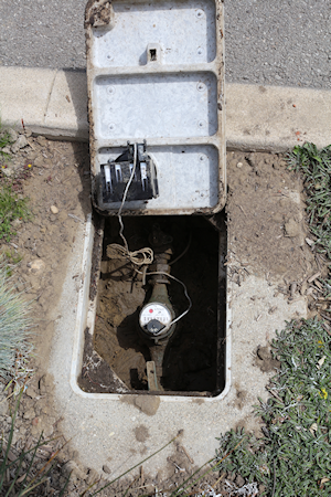
Flow Sensors (optional)
Some people install their own water metering device on the irrigation system main supply pipe so they can monitor just the irrigation water usage. A flow sensor rather than a water meters is used for this. The difference between the two is that a typical water meter measures only the amount of water used, flow sensors measure the rate of flow. This allows them to monitor how much flow the irrigation system is using at any given moment. The flow sensor typically creates an electronic pulse when a given amount of water has passed through it, for example a cubic foot of water. The flow sensor connects up to the irrigation controller that is used to turn on and off the irrigation system. Some higher-end models of irrigation controllers have the ability to monitor the number of pulses from the sensor and use the data to determine how much water is flowing at the moment, as well as the total amount of water used per irrigation cycle. Using this information the controller can evaluate the irrigation system performance and respond to it. For example the controller might detect that the flow is higher than normal, indicating a leak in the irrigation system, or maybe a broken sprinkler head. Likewise a flow that is lower than expected might indicate a valve did not open when it was supposed to. The controller then sounds an alarm, or may shut off the water to limit damage from the leak. Flow sensors and controllers that monitor flow are features that are common on many larger irrigation systems, like parks and golf courses. Now, as the price of the equipment is rapidly dropping and water conservation is becoming an issue in more places, homeowners are starting to implement these optional flow sensing features as well. Controllers that have this monitoring feature are called “Smart Controllers”. Note that not all Smart Controllers have this monitoring feature. For more information see the article on Smart Controllers.
If the meter is buried in a box, be careful when you open the box. Over the years I’ve encountered just about every creepy thing one can imagine in those boxes! Turtles, rats, snakes, various dead things. Ants and spiders are most common. It’s not a bad idea to be prepared to jump back, and maybe have a can of bug killer handy when opening a underground box. Once you find the meter you will likely need to clean it off so you can clearly see it. The meter should have a size stamped on it, if not, sometimes the meter size is shown on your water bill. If all else fails, call your water company and ask them for the meter size. The size should be in their water billing information. The pressure loss (PSI Loss) for water meters is based on the meter size and the flow rate. If you know the brand of the water meter you can probably find a table on the manufacturer’s website that tells you the pressure loss for the meter size at various rates of flow. If not, the charts below should be close enough.
The charts below give typical pressure losses for various meter sizes and flow rates. If your meter is a combination of two sizes (like 5/8 x 3/4) use the chart for the smaller size. These dual-size meters are made by taking a small meter and putting a larger size inlet and outlet on it. So it is really the smaller size meter. For flow sensors you will need to contact the sensor manufacturer to find out how much pressure loss to expect in your unit. Flow sensor losses are generally less than those for a standard water meter, so if you can’t find a manufacturer’s flow loss table, in most cases you can safely use the values in the water meter tables below for flow sensors.
![]() Find your meter size below, then use your “Initial Design Flow” (from your Design Data Form) to find the PSI loss. Enter the PSI loss from the table below on the water meter line of the Pressure Loss Table. If you don’t have a water meter just enter 0 on the table. If you modify the Initial Design Flow later you should come back and change the water meter/flow sensor PSI Loss values as well. (This will be true of all your PSI Losses in the Pressure Loss Table that are based on flow. If you change the Design Flow for your system you will need to update the PSI Loss values. There is a bit of trial and error to the irrigation design method as you attempt to find that “sweet spot” that balances pressure vs. flow to give the optimum performance.)
Find your meter size below, then use your “Initial Design Flow” (from your Design Data Form) to find the PSI loss. Enter the PSI loss from the table below on the water meter line of the Pressure Loss Table. If you don’t have a water meter just enter 0 on the table. If you modify the Initial Design Flow later you should come back and change the water meter/flow sensor PSI Loss values as well. (This will be true of all your PSI Losses in the Pressure Loss Table that are based on flow. If you change the Design Flow for your system you will need to update the PSI Loss values. There is a bit of trial and error to the irrigation design method as you attempt to find that “sweet spot” that balances pressure vs. flow to give the optimum performance.)
| 5/8″ meter | |
|---|---|
| 5 GPM | 1 PSI loss |
| 7 GPM | 2 PSI loss |
| 9 GPM | 3 PSI loss |
| 11 GPM | 4.5 PSI loss |
| 13 GPM | 6 PSI loss |
| 15 GPM | 8.3 PSI loss |
| Don’t exceed 15 GPM | |
| 3/4″ meter | |
|---|---|
| 4 GPM | 0.5 PSI loss |
| 8 GPM | 1 PSI loss |
| 11 GPM | 2 PSI loss |
| 14 GPM | 3 PSI loss |
| 17 GPM | 5 PSI loss |
| 20 GPM | 6.5 PSI loss |
| Don’t exceed 20 GPM | |
| 1″ meter | |
|---|---|
| 8 GPM | 0.5 PSI loss |
| 13 GPM | 1 PSI loss |
| 19 GPM | 2 PSI loss |
| 23 GPM | 3 PSI loss |
| 26 GPM | 4 PSI loss |
| 29 GPM | 5 PSI loss |
| 32 GPM | 6 PSI loss |
| 34 GPM | 7 PSI loss |
| Don’t exceed 34 GPM | |
1 1/4″ meter:
(This is not a standard water meter size. If you have one it is probably a 1″ meter modified to have a 1 1/4″ inlet and outlet. But, then again, it might be a 1 1/2″ modified to 1 1/4″. Not very helpful? Unless you are reasonably sure by looking at it that it is a 1 1/2″, you should assume it is 1″.)
| 1 1/2″ meter | |
|---|---|
| 17 GPM | 0.5 PSI loss |
| 22 GPM | 1 PSI loss |
| 31 GPM | 2 PSI loss |
| 38 GPM | 3 PSI loss |
| 45 GPM | 4 PSI loss |
| 50 GPM | 5 PSI loss |
| 55 GPM | 6 PSI loss |
| 60 GPM | 7 PSI loss |
| Don’t exceed 60 GPM | |
| 2″ meter | |
|---|---|
| 36 GPM | 1 PSI loss |
| 51 GPM | 2 PSI loss |
| 63 GPM | 3 PSI loss |
| 72 GPM | 4 PSI loss |
| 82 GPM | 5 PSI loss |
| 88 GPM | 6 PSI loss |
| 100 GPM | 8 PSI loss |
Contact manufacturer for larger size meters.
That wasn’t hard, was it? You’re gonna fly through this!
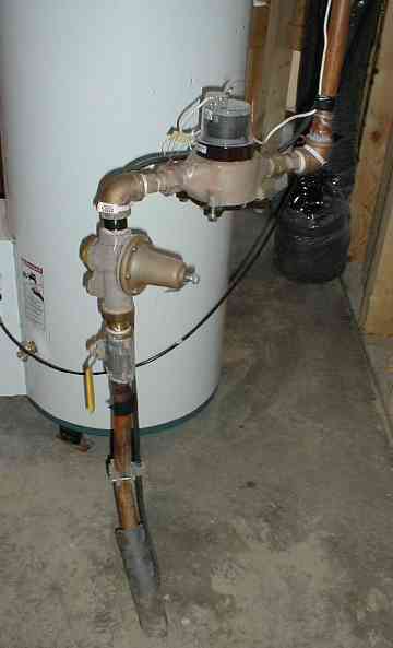
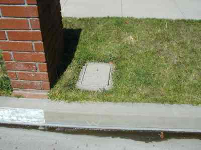
This article is part of the Sprinkler Design Tutorial Series
<<< Previous Page ||| Tutorial Index ||| Next Page >>>
By using this tutorial you agree to be bound by the conditions and limitations listed on the Terms of Use page.
Selecting Your Sprinkler Equipment
In this step you will make some preliminary selections of the equipment such as sprinkler heads, valves and more. When selecting your sprinkler equipment we need to also find out how much pressure loss each item creates. The amount of pressure loss may require that you reconsider one product over another. Keep reading and it will become clearer.
![]()
Like all other mechanical systems an irrigation system consumes energy when it operates. The irrigation system uses energy in the form of water pressure which, as we noted earlier, we will be measuring in PSI (pounds per square inch). Each component in the irrigation system that the water passes through consumes a little bit of that water pressure. It’s similar to how a car uses up fuel for each mile it goes. If we run out of water pressure before the water makes it through the system, then the irrigation system will not work. Therefore, we need to calculate how much pressure will be lost as the water passes through each component of the irrigation system. To start we will need to make some educated guesses, which are then confirmed and adjusted by using a trial and error process. Don’t worry, it’s easy to do…
Below is a Pressure Loss Table that lists items that you MAY need to factor into your pressure loss calculations. Some of the items may not be necessary in some situations. The tutorial has a page for each of the items that will tell you everything you need to know. I will explain to you all the pros and cons of the various product types available. For the more complex choices like backflow preventers, I will lead you through a series of simple questions that will guide you toward the best solution for your specific irrigation system. Then you will pick your actual equipment and enter the associated pressure loss value into the Pressure Loss Table on your Design Data Form.
![]()
Near the bottom half of your Design Data Form there is a copy of the Pressure Loss Table below.
Hopefully you picked up a copy of the Design Data Form earlier in the tutorial. If not, please go back to the appropriate page for your water supply source below so you can figure out the correct values for available GPM, PSI and get the form:
City Slicker Water. Water supply from a water company, utility, or district.
Country Bumpkin Water. You use a pump to get water from a well, stream, pond, etc.
Backwoods Water. Gravity flow water system from a tank or spring. No pump.
You’ll refer back to these values several times throughout the design process and you may need to change them a few times, so use a pencil so you can erase and rewrite values! If you have bad handwriting skills like me, you may wish to write a bit neater than normal so you can read it later! There’s nothing worse than having to go back and recalculate your data because you can’t read your own handwriting. Believe me, I’ve had to do it way too many times! If an item on the table doesn’t apply (for example, you don’t have a water meter) just enter n/a and a pressure loss value of 0 for that item.
OK, here’s a typical Pressure Loss Table.
Pressure Loss Table
| Item (links jump to a page with details on each item) | Brand & Model | PSI Loss |
|---|---|---|
| Water Meter | ||
| Flow Sensor (optional) | ||
| Master Valve (optional) | ||
| Backflow Preventer | ||
| Filter (optional but strongly suggested) | ||
| House Mainline 1 (pipe to house) | ||
| House Mainline 2 (pipe through house or to irrigation connection) | ||
| Irrigation Mainline | ||
| Valves (remote control valve, zone valve) | ||
| Elevation change (change in feet x .433 = PSI) | ||
| Sprinkler Heads or Drip Emitters | ||
| Lateral (“branch”) Pipes (20% of sprinkler head PSI Loss maximum) | ||
| Total Pressure Loss (add together the values above.) |
Don’t panic! The next few pages of the tutorial goes through each item on this table and helps you to figure out the pressure losses to enter on each line of the table. If you’ve used the tutorial before and already know a lot of this, the links in the table above will allow you to jump ahead in the tutorial to the page where the details on that item are located. For most people you will want to just keep reading the pages in order.
Pressure Regulators & Pressure Reducers
Before we continue on we need to address pressure regulators/reducers. (You will see them also called a “pressure reducing valve,” “pressure regulating valve,” and various other names. I’m going to use the name “pressure regulator” to avoid confusion.) A pressure regulator is a special valve that reduces the water pressure to a set level and keeps it at that level. Some homes have these pressure regulators installed on the water supply, which can impact the values used in the Pressure Loss Table. If you have a municipal water supply, you already learned a little about pressure regulators on the City Slicker Water page of the tutorial. Back on that page you should have discovered if you have a pressure regulator and, if you do, you also decided if you would tap into your water supply before or after that pressure regulator.
If you have a pressure regulator on your house then you get to take a little shortcut. On your pressure loss table you get to ignore the pressure loss for everything upstream of the pressure regulator.
Installing a Pressure Regulator
If you are planning to install a new pressure regulator be aware that there are two types sold. The one you want to use on your house will be made of bronze or brass, it should have a pressure adjustment screw so you can set the downstream pressure you want, and generally it’s going to be pretty expensive. If you need one for a sprinkler system I suggest it also be this more expensive type. There are also cheaper pressure regulator models that use a different principle to work. These cheaper pressure regulators are often used on drip irrigation systems. They are not adjustable, are not nearly as accurate, and will often allow a damaging pressure surge to pass through them. They typically are barrel-shaped and constructed of plastic. They will not have a adjustment screw or knob on them.
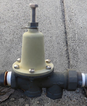
Before you decide to take a shortcut and install a pressure regulator right before the valves so you can ignore pressure loss in the mainline, consider that the higher pressure may not be good for those upstream components. Generally I try to avoid pressures over 100 PSI in any portion of my sprinkler systems. I strongly recommend that you do likewise. Also remember that maximum water velocities also still apply to the mainline pipes, so you will still have to do the size calculations for the mainline.
When placing a pressure regulator on an irrigation system I normally install it right after my main irrigation system shut-off valve at the place where I tapped into the water supply. Thus I have:
connection to water supply –> emergency shut-off valve –> pressure regulator –> irrigation system.
Don’t forget the pressure setting of a pressure regulator must always be at least 15 PSI lower than the incoming pressure. If the incoming pressure is 80 PSI the pressure regulator must be set at 65 PSI or less. Otherwise the pressure regulator will not work accurately and may allow damaging pressure surges to pass through it. To restate this another way, the pressure regulator must reduce the pressure by 15 PSI or more for it to work accurately and reliably.
This article is part of the Sprinkler Design Tutorial Series
<<< Previous Page ||| Tutorial Index ||| Next Page >>>
By using this tutorial you agree to be bound by the conditions and limitations listed on the Terms of Use page.
How to Find Your GPM & PSI – Pumps and/or Wells
![]()
STOP! If you mess this up you can ruin your pump! Read this! Most do-it-yourself sprinkler design tutorials are not suitable for rural irrigation systems that use pumps!!! Be very careful if you are also looking at one of them for guidance. The methods they use to determine water supply are little better than taking a wild guess. You’ll understand after reading this page.
If you are going to use this tutorial (and you should!) you need to use ONLY this tutorial. If not, you are going to be in big trouble. A large number of questions I get from people who are confused are caused because they are trying to mix together this tutorial with some other guide or tutorial, or maybe it was advice they got from some well-meaning, but clueless, salesman. Even many professional irrigation contractors do not understand the hydraulics of systems using pumps! Use this tutorial exclusively and save yourself a lot of grief and get a professional quality sprinkler system. Please, please, please! Thank you. You are helping save my sanity. Now on with the tutorial.
Sorry this is such a long page, but pumps are tricky. There is a lot you need to know. You can really mess up big time with a pump and an irrigation system if you do it wrong. So please be patient, read carefully, then reread it all again. Try working the examples, it helps the old brain to kick in!
None of that domesticated city water for you! You have your own pump and water source! That may be a well, river, pond, lake, or the ocean. (Ocean water? Are you growing seaweed?) Unfortunately, pumps are tricky and so you’re going to have to do a bit more work than you would if you had a “City Slicker” water supply. If you have a well, you have probably been told at some time or another that you have a “XX GPM well”. Do NOT rely on that figure! That is most likely the capacity of your well, not the output of your pump, and there is a big difference between the two. There may also be a GPM & PSI noted someplace on the pump, pump panel, literature, or the box the pump came in. Same deal. Don’t rely on these numbers; they assume optimum conditions that exist pretty much only in the pump company’s test facility. You’re going to have to do a little research, do some tests, probably get wet, and do a few calculations. I don’t recommend calling your pump and well company and asking them for the GPM of your well or water system. While some have given me a correct figure, more have given me an incorrect one! It’s not that they want to lie to you, it’s just that there are several terms here that can be easily confused. If the figure they give you is too high, your irrigation system will not work, period. If it is too low you will burn up your pump. I have written a complete tutorial on pumps and related equipment. I strongly suggest the Pump Tutorial if you would like to know more about your pump system, or if you want to know more of the reasoning behind what follows on this page. Click here to go to the Pump Tutorial.
![]()
If you have a printer, there is a Design Data Form that will make things easier for you. If you would prefer a pdf version of the form PDF Design Data Form.
![]()
Planning to buy a pump or install a well, but don’t have it yet? First, if you have a well, you will need to know the GPM of the well itself. That’s not how much you will pump out of it, that’s the maximum the well will provide. Your well driller should have measured this when the well was drilled, if not you will need to have the well tested by a well drilling company. They will install a temporary pump in the well to test the output. Then you need to select a random Design Flow and Design Pressure. I suggest 20 GPM per acre and 50 PSI, as those are good starting values. Example: If you have a 2.5 acre mini-ranch you would want to use 50 GPM at 50 PSI. Now proceed with a trial irrigation design using those values. Once you have finished the trial design, you will have discovered whether those are good values for your sprinkler system. If not, what would be? Redesign it if you have to. I know, that’s a lot of work, I agree, but it is far easier to redesign it on paper than to try to fix it after it is installed! Once you have established a good Design Flow and Design Pressure it’s time to shop for a pump. Remember the Design Pressure is at the irrigation connection point, the pump will also need additional pressure to lift the water from the well or pond (see the pump tutorial.) After you have your pump installed and running, test it using the Wet Method below. Then create your final sprinkler design based on those results. I know this sounds like a lot of extra effort, but the result will be an almost perfectly matched pump and sprinkler system. It will be worth the effort! You should absolutely read the Pump Tutorial.
![]()
So-called “Sprinkler Pumps” and packaged pumps. Several retail hardware store chains sell what they call “sprinkler pumps”. They are also sold on a number of web sites and, of course, Ebay. At least one of them even calls their pump a “High Pressure Sprinkler Pump.” Sorry, but not by any stretch of the imagination! Typically these pumps do not provide enough water pressure for a standard sprinkler system, especially if you are on a hilly site or pumping from a water source that is more than 10 feet below the pump. (See the paragraph above for suggested pressures.) These pumps will operate small sprinkler heads on a level lot, using water from a shallow well. Few people outside of Florida have this situation. These pumps are really best suited for use as booster pumps. In general, they do not produce enough water pressure for automatic sprinkler systems. Also watch out for packaged pumps that say they are rated X GPM and X PSI on the box (insert any values for “X”.) Often these two performance figures are both the maximums possible for the pump, which may be accurate, but is also misleading. When a pump is operating at it’s maximum GPM, it will also be at the minimum PSI. There is an inverse relationship between the two values. With pumps (and this applies only to pumps) as the output pressure (PSI) goes up, the output flow (GPM) goes down. Often the figure they give you on the box is the maximum possible for each value. (Read the Pump Tutorial.) Just be very careful. Design your sprinkler system FIRST, then buy your pump! If your calculations say you will likely need a 1.5 HP pump, and you find a 1/2 HP pump at the store that says it will do the job, be very suspicious.
Measuring Pump Output:
By the way, this looks complicated but it’s really pretty simple if you take it step-by-step! There are two ways to do this; The Dry Method and The Wet Method. I suggest you read through both of the methods, and try both of them if possible.
The Wet Method is more accurate (but only when done correctly.) The advantage to the Dry Method is that it gives you a chance to check the condition of your pump. If the Dry Method results in a much higher GPM and flow than the Wet Method, then it probably means your pump is worn out. Consider replacing your pump.
![]()
If you think you may be getting a new pump in the next 5 years, wait until you have the new pump installed before designing your sprinkler system! A new pump will likely have much better performance than the old one. If you designed your sprinkler system for the old pump then it will not work well with the new one, and may even damage the new pump!
Submersible Pumps. Many people have submersible pumps. In those cases the pump is located down inside the well, rather than on top of the well as in the diagram above. All the calculations work the same regardless of where the pump is.
Dry Method
First you need the horsepower of your pump. This may be stamped on the well, on the pump, on the pump panel, or your pump company should have a record of it. You may notice a GPM and PSI stamped on the pump plate also. I’ll say it again because it’s important: don’t rely on these numbers!
![]()
(A) Enter your pump horsepower on the Design Data Form.
What if you don’t have a well? If you don’t pump out of a well, substitute river, lake, pond, spring, mud-puddle, or whatever for “well” in the following procedures. In this case “water level when pump is running” is the lowest expected water level in your pond, stream, etc. (i.e.; the level the water would be in a really dry year.) You obviously also don’t have a “top of well”, so for a submersible pump when the tutorial mentions the “top of well” you would use the highest possible water level of your water source. If the pump is mounted above the water level (non-submersible), then you will need to substitute the actual pump location for “top of well” in this tutorial.
When using a non-submersible pump (any pump not below the water level) it is very important that the pump be installed as close to the water surface level as possible. Pumps are made to push water, not to pull it. The farther and higher the pump has to pull the water, the less efficient the pump will be. Some pumps work better than others in this situation, but in general expect trouble if the pump is more than 10 feet higher than the water surface. The higher your elevation is above sea level, the closer the pump needs to be to the water level. Therefore, in Denver, Colorado, the “Mile High City”, you need to have your pump very close to the water surface (or better yet, use a submersible pump.) Also, avoid long intake pipes between the water and the pump. Long intake pipes/manifolds can also hurt the pump performance. Plus, a long intake pipe is more likely to have a leak in it, and a leak in the intake pipe can cause your pump to lose prime. Losing the pump prime is a real pain in the rear, and if you automate your system it can cause serious damage to the pump. The bottom line here is to keep the pump as close to the water as possible.
Now you need to find out the “Dynamic Water Depth” of the water in your well. Your pump company may have a record of this, however you really should have the well “sounded” to get a new reading, especially if the well is more than 5 years old. Water levels often drop over time. As a last resort you can use the pump depth or well depth, but if you do, you may experience expensive pump problems later. Better to sound the well now. This is something your pump company can do for you and in most cases, is relatively easy and inexpensive. If you don’t have a well (you have a pond, creek, etc.,) use the lowest “dry year” water level of your water supply.
As you can see from the diagram above, the Dynamic Water Depth is the distance in feet between the top of the well and the water level in the well when the pump is running (dynamic means moving, as in the water is moving when the depth is measured.) It is important that the pump be running when this is measured. This is because when the pump runs, the water level in the well drops. The distance it drops is known as “draw-down”. The further the pump must lift the water, the more energy it takes. So as the water level gets deeper, the pump will produce less water pressure (water energy) at the outlet. That energy (water pressure) is what runs the sprinklers, so you must have an accurate measurement of it. You need to measure the Dynamic Water Depth, not just the depth of the water table.
![]()
As you know, water flows downhill. When the pump runs it pulls water out of the well. This causes the water level to drop, and then water flows into the well from the surrounding soil. How far the water level drops depends on how hard it is for the water to move into the well from the soil. Some wells have very little draw-down, others may have 50 feet or more of draw-down. Don’t worry if you don’t understand, it will all come together later!
![]() (B) Enter your “Dynamic Water Depth” on your Design Data Form.
(B) Enter your “Dynamic Water Depth” on your Design Data Form.
Now you need to enter the elevation difference between the top of your well and the highest point in the area to be irrigated. That is, how much higher (or lower) is the highest point in the irrigated area than the top of the well. The best way to do this is to use a laser level and a tape measure. Place the laser level at the high point of the irrigation system and shoot a level beam toward the well. Then use the tape measure to measure the distance from the laser beam to the top of the well. That is the elevation difference. You may need to make several stepped measurements, or you may prefer to just make an educated guess at the elevation difference rather than try to measure it. Also, if the well is higher than the irrigated area the distance will be a negative number.
![]() (C) Enter your elevation difference on your Design Data Form.
(C) Enter your elevation difference on your Design Data Form.
Add the elevation difference to the Dynamic Water Depth of the well (or subtract if it’s negative). This number (in feet) is called “elevation head” and is a measure of the height the pump must push the water to get it to your irrigation system.
![]() (D) Enter your elevation head on your Design Data Form. B + C = D (Dynamic Water Depth + elevation difference)
(D) Enter your elevation head on your Design Data Form. B + C = D (Dynamic Water Depth + elevation difference)
One more thing needs to be factored in at this point, which is your Design Pressure. The Design Pressure is the amount of water pressure that is needed at the inlet of the irrigation system in order for the system to operate. Design Pressure is measured in PSI (pounds per square inch), but for this formula we need the pressure as measured in feet of head. To convert PSI to feet of head we simply multiply PSI times 2.31.
PSI x 2.31 = Feet Head (ft.hd.)
Well that’s all fine and dandy, but what IS our Design Pressure you ask? Good question! Guess what? “Guess” is the operative word here. You’re going to need to take an educated guess at this number. For most situations I recommend that you use a Design Pressure of 50 PSI. This is a good number that works with most small to mid-size irrigation systems. For sprinkler systems with large radius sprinklers (over 35′ between sprinkler heads) you will need a higher Design Pressure. A good rule of thumb for large systems is to take the distance you would like to have between sprinkler heads in feet, and add 15 to it to get a reasonable Design Pressure. For example, if you want to put the heads 50 feet apart, you will need a design pressure of 65 PSI (50 + 15 = 65). Don’t be surprised if your system won’t pump 65 PSI, most residential pump systems aren’t designed to supply more than 50 PSI. As a side note keep in mind that higher Design Pressures result in lower flows, so the higher the pressure, the more valves you will need. I do not recommend spacing sprinkler heads farther apart than 50 feet without having a professional design the system! It gets very tricky. Even most City parks now keep the spacing between sprinklers at 55 feet or less.
![]() (E) Enter your desired “Design Pressure (PSI)” on your Design Data form. For most of you this will be 50 PSI as discussed above. Remember this number is not written in stone! You may want to try adjusting it up and down.
(E) Enter your desired “Design Pressure (PSI)” on your Design Data form. For most of you this will be 50 PSI as discussed above. Remember this number is not written in stone! You may want to try adjusting it up and down.
Now we need the “Design Head” so multiply Design Pressure (PSI) times 2.31 to convert it to feet head. This is just a conversion from one type of pressure measurement (PSI) to another (Feet Head). Pump calculations always measure pressure in Feet Head. Example: 50 PSI x 2.31 = 115 ft.hd. (rounded down from 115.5)
![]() (F) Multiply your Design Pressure by 2.31 and enter it as “Design Head” on your Design Data Form.
(F) Multiply your Design Pressure by 2.31 and enter it as “Design Head” on your Design Data Form.
Now we put all these numbers together to get our “total pressure head”. Total pressure head is the “elevation head” plus the “design pressure head”, all in feet of head.
elevation head (ft hd) + design pressure head (ft hd) = total pressure head (ft hd)
Example:
30 ft. Dynamic Water Depth is measured in well with the pump running. The high point of yard is 10 ft. higher than top of well. 50 PSI Design Pressure, which equals 115 feet of design pressure head.
Total Pressure Head = 30 + 10 + 115 = 155 ft. hd.
Another Example:
Pumping from a lake. The low water level is 20 ft. below the high water level. The lowest point of the irrigation system is 10 ft. higher than the high water level. 45 PSI Design Pressure (104 feet head).
Total Pressure Head = 20 + 10 + 104 = 134 ft. hd.
Yet another Example:
For a small park, pumping from a canal. We use the canal bank as our “top of well” level. The low water level in the canal is 8 ft below the top of bank. The irrigation system is downhill from the canal, 25′ below the top of bank. 65 PSI Design Pressure needed for large turf sprinklers, which equals 150 feet of design pressure head (65 * 2.31 = 150 ft hd).
Total Pressure Head = 8 – 25 + 150 = 133 ft. hd.
![]() (G) Calculate your “Total Pressure Head” and enter it on your Design Data Form.
(G) Calculate your “Total Pressure Head” and enter it on your Design Data Form.
Now for the flow formula:
Multiply the pump Horsepower times 2178 (a constant value, see note at bottom of this page) and then divide by the Total Pressure Head in feet.
Horsepower x 2178 / Total Pressure Head (feet) = GPM (the “Design Flow”)
So for the first example above with a 2 h.p. electric pump:
2 h.p. x 2178 / 155 ft. hd. = 28 GPM Design Flow That’s it! The GPM resulting from the above formula is your “Initial Design Flow”. You will need the Initial Design Flow and Design Pressure values later in the tutorial.
![]() (H) Calculate your “Initial Design Flow” and enter it on your Design Data Form.
(H) Calculate your “Initial Design Flow” and enter it on your Design Data Form.
![]() Caution: When designing a sprinkler system with a pump you want to keep the actual flow of each valve zone as close to the “Design Flow” as possible without exceeding the Design Flow. This is to keep the pump from cycling on and off as it tries to match the demand of your irrigation system. Don’t worry about valve zones now, we’ll have more on that later. Just remember this: “Valve Zone GPM must be between 80% and 100% of Design Flow”. You may want to write that down someplace. Technical note: In order to simplify the pump formula I have factored a pump efficiency of 55% into the value of the formula constant (2178).
Caution: When designing a sprinkler system with a pump you want to keep the actual flow of each valve zone as close to the “Design Flow” as possible without exceeding the Design Flow. This is to keep the pump from cycling on and off as it tries to match the demand of your irrigation system. Don’t worry about valve zones now, we’ll have more on that later. Just remember this: “Valve Zone GPM must be between 80% and 100% of Design Flow”. You may want to write that down someplace. Technical note: In order to simplify the pump formula I have factored a pump efficiency of 55% into the value of the formula constant (2178).
![]() Pressure Up, Flow Down?!!! Wait a minute here! It seems like what this formula says is that if the pressure goes down the flow goes up! That just doesn’t make sense. What gives? O.K., by popular demand, here’s an answer to this little dilemma. It’s one of those obscure, hard to understand hydraulic principles I was yapping about earlier. Sit back. Grab a nice soothing cup of tea or whatever. Put on some soft, relaxing background music. Ready? Here we go… I know it doesn’t SOUND logical, but believe me it IS correct. You’re thinking if more pressure is added then more water will be moved, which is true, but you’re talking about ADDING pressure, not using the AVAILABLE pressure! And that is the key to the problem. Remember we are measuring your AVAILABLE pressure and flow, based on the current conditions at your house (or whatever).
Pressure Up, Flow Down?!!! Wait a minute here! It seems like what this formula says is that if the pressure goes down the flow goes up! That just doesn’t make sense. What gives? O.K., by popular demand, here’s an answer to this little dilemma. It’s one of those obscure, hard to understand hydraulic principles I was yapping about earlier. Sit back. Grab a nice soothing cup of tea or whatever. Put on some soft, relaxing background music. Ready? Here we go… I know it doesn’t SOUND logical, but believe me it IS correct. You’re thinking if more pressure is added then more water will be moved, which is true, but you’re talking about ADDING pressure, not using the AVAILABLE pressure! And that is the key to the problem. Remember we are measuring your AVAILABLE pressure and flow, based on the current conditions at your house (or whatever).
If we were planning to add a big pumping system then we would use a different approach. The correct way of looking at it is “how much water can we move with the pressure that your existing pump can supply?” It takes energy to move water, and the water pressure is the energy that is used. As the water is moved, the energy is used up. Therefore, the water pressure goes down. The more water is moved, the more of the existing pressure is consumed moving it. As the flow (GPM) of the water increases, the pressure (PSI) of the water must decrease! (This is because the pressure is used up moving the water.) Does that make sense? Well, even if you don’t get it, that’s O.K. It takes most engineering students 2-3 months of college level class work before they fully understand hydraulics, so don’t feel bad if it still doesn’t make sense. You’ll just have to believe me that it’s correct (and don’t worry, it is!)
Wet Method (Also called the “Bucket Method”)
This is the most accurate way to test your pump. BUT… Before we start into this I need to warn you that you must follow the instructions below exactly. Do not skip any steps, do not shortcut. If you do not follow these steps exactly you will get a false reading, your sprinkler design will not work, and you probably will destroy your pump! Understand?
![]() Sprinkler systems need pressurized water to operate. Without the pressure, the water doesn’t shoot out of the sprinklers! Think of water pressure as the “energy” that moves the water. Just measuring the water flow with a bucket is not good enough, we must also measure the water pressure at the same time, as we need that pressure to make the sprinklers spray water. If you had a city water supply we would measure the “Static Water Pressure”. This is the pressure when the water isn’t moving. The amount of water available on a city water system is determined by the size of the pipe supplying the water. For a pumped system the amount of water available is determined by the size of the pump. When using a pump we must measure the “Dynamic Water Pressure” also. Dynamic water pressure is the pressure of moving water. Dynamic pressure will always be lower than static pressure. This is because when the water is moving friction is created with the edges of the pipe. This friction consumes energy (remember, pressure is energy) so the pressure drops. The faster the water moves, the more friction, so the pressure is reduced even more. When pumping water there is an inverse relationship between flow and pressure, if you want to get more pressure, then you are going to get less water flow. If you just turn on a faucet and measure the flow into a bucket the pressure falls to zero (the water just falls into the bucket, therefore no water pressure.) That results in a higher than normal flow (lower pressure = higher flow.) To make matters worse, most people measure the flow from a standard faucet. The small size of the faucet restricts the flow, adding more error to the measurement. If you’re lucky the errors balance each other out, but most of the time that isn’t going to happen. Add in a little sloppy measuring, and the results can be off by 20% or more. That can be enough to cause your pump to cycle, which will result in pump failure. Replacing pumps is a major expense, so let’s do this thing right. It takes more time and effort, but it will be worth it. Need to know what size your pipe is? How to find the size of a pipe.
Sprinkler systems need pressurized water to operate. Without the pressure, the water doesn’t shoot out of the sprinklers! Think of water pressure as the “energy” that moves the water. Just measuring the water flow with a bucket is not good enough, we must also measure the water pressure at the same time, as we need that pressure to make the sprinklers spray water. If you had a city water supply we would measure the “Static Water Pressure”. This is the pressure when the water isn’t moving. The amount of water available on a city water system is determined by the size of the pipe supplying the water. For a pumped system the amount of water available is determined by the size of the pump. When using a pump we must measure the “Dynamic Water Pressure” also. Dynamic water pressure is the pressure of moving water. Dynamic pressure will always be lower than static pressure. This is because when the water is moving friction is created with the edges of the pipe. This friction consumes energy (remember, pressure is energy) so the pressure drops. The faster the water moves, the more friction, so the pressure is reduced even more. When pumping water there is an inverse relationship between flow and pressure, if you want to get more pressure, then you are going to get less water flow. If you just turn on a faucet and measure the flow into a bucket the pressure falls to zero (the water just falls into the bucket, therefore no water pressure.) That results in a higher than normal flow (lower pressure = higher flow.) To make matters worse, most people measure the flow from a standard faucet. The small size of the faucet restricts the flow, adding more error to the measurement. If you’re lucky the errors balance each other out, but most of the time that isn’t going to happen. Add in a little sloppy measuring, and the results can be off by 20% or more. That can be enough to cause your pump to cycle, which will result in pump failure. Replacing pumps is a major expense, so let’s do this thing right. It takes more time and effort, but it will be worth it. Need to know what size your pipe is? How to find the size of a pipe.
Pump and Pressure Tank Example #1:
The light green colors are the new pipes added for the test. Later you can use this new pipe for the supply pipe (mainline) for your sprinkler system supply tap, so installing this isn’t a waste of money. When the pipe from the pump goes into the tank and then another pipe comes out and goes to the house you should make your tap after the tank as shown. Note that the pressure tank may not be near the pump, especially in cold winter areas where the tank is often installed in the house basement. The new piping can be vertical if you wish, and you can add ells to the last section to get the pipe over the top of the bucket. The 8″ straight lengths of pipe before and after the pressure gauge are important, they must be 8″ long and there can’t be any ells in these sections. The purpose is to avoid creating turbulence in the water that could affect the pressure gauge accuracy.
Pump and Pressure Tank Example #2:
When the pressure tank only has a single pipe going into it you can tap the pipe anywhere. You can tap it between the pump and pressure tank as shown, or after the pressure tank. Most pressure tanks are set up this way. Note that the pressure tank may not be near the pump, especially in cold winter areas where the tank is often installed in the house basement. The new piping can be vertical if you wish, and you can add ells to the last section to get the pipe over the top of the bucket. The 8″ straight lengths of pipe before and after the pressure gauge are important, they must be 8″ long and there can’t be any ells in these sections. The purpose is to avoid creating turbulence in the water that could affect the pressure gauge accuracy.
Wet Method Test Step-by-Step:
![]() Follow the instructions below exactly!
Follow the instructions below exactly!
1. Select the location where you will connect the sprinkler system into your water system (your “tap location”). See the pump and pressure tank example diagrams above. In some (very few) pump systems you must tap the pipe after the pressure tank as in Example #1 (see example #1 above.) However, most systems are like Example #2, so you can tap into the water supply line anywhere you want. In this case it is often best to tap as close as possible to the pump. This will usually give you a higher pressure, which means a better sprinkler system (and often less expensive, too!) In some cases you may want to connect your new irrigation system into an existing pipe somewhere a considerable distance away from the pump, such as a faucet near a garden. This is fine, go ahead and try it. The problem is that often the existing pipe is not large enough. You may find that you don’t get a very high water pressure due to the small pipe. If this happens you can confirm the problem by making another tap near the pump and testing there also. If you get a much higher pressure and flow when you test near the pump, then the existing pipe is too small.
2. If there is already an outlet on the pipe at your desired tap location you may use it for the test, provided the outlet is the same size as the pipe coming from the pump. If there is not already an outlet you will need to cut the pipe and install one as follows. Measure the size of the pipe. Go to the hardware store and purchase a compression tee that will fit the pipe. Have the sales person show you how it works. I suggest using a metal compression tee rather than plastic. The side outlet of the compression tee should be the same size as the pipe you are tapping into. At your tap location, cut a short section out of the pipe out and install the compression tee.
Note, sometimes it is necessary to brace the compression tee in place to prevent it from moving and slipping off the pipe. In some situations compression tees will not work. In that case you may need to install a threaded or glue in place (pvc pipe only) tee. If you have the time and skill to install a threaded or glued tee, that is always a better option than a compression tee.
3. Install the parts shown in green as per the Wet Method Pump Output Test sample drawings above as follows:
Start with an 8″ long pipe section installed on the (compression) tee outlet, then another tee with a 0-100 PSI pressure gauge on it, then another 8″ long pipe section, then a ball valve, then add a temporary PVC pipe (maximum of 4 feet of pipe with 3 ells) so that you can fill a 5 gallon bucket to measure the water flow. All the pipes and the valve should be the same size as the pipe you cut to make the tap. Do not use a garden hose as it will restrict the flow and give you a false low flow reading! I strongly suggest using metal pipe and fittings between the tap and the ball valve. I also suggest using a brass (or bronze) ball valve. This ball valve will become the shut-off valve for your future sprinkler system. The last pipe section going to the bucket after the ball valve is temporary and can be plastic. See the example drawings above. The rest of this test process is going to dump a lot of water on the ground, so now is a good time to figure out where that water will go, before you’re up to your knees in mud!
4. Get a “5 gallon bucket”. Since most 5 gallon buckets actually hold more than 5 gallons of water you probably will need to “calibrate” it and mark the actual 5 gallon volume level on the side of the bucket. Fill it with 5 gallons of water using an accurate measuring container to measure the water, then mark the water level on the bucket with a marking pen so you can easily see it. Empty the bucket.
5. Open the ball valve and allow the water to flow freely from it for at least 5 minutes so the flow from the pump can stabilize. ( If your pump is manually controlled you will have to manually start it.) Assuming you have a pressure controlled pump like most are, the pump should start by itself and run continuously during this time.
If the pump shuts off by itself when running with your test outlet full open you have an unusual problem, probably too much restriction in the piping. First check to see if there is any kind of restriction in the pipe (I’ve found rocks, toy cars, rags, rats, fish, roots, etc. in pipes). If not, the pipe from your well may be too small. Best to call a pump company for help at this point as something is seriously wrong with the pumping system.
6. With the pump running, watch the PSI reading on the pressure gauge, and slowly start closing the ball valve until the pump shuts off. The water pressure shown on the gauge will increase as you close the valve. (As the flow from the pump is reduced the pump produces more pressure.) Make a mental note of the pressure when the pump shut off.
7. Reopen the ball valve and wait for the pump to start again. Now slowly close the ball valve again until you find the point at which you get the highest possible pressure reading on the gauge without the pump shutting off. When you find this “balance point” the pump should run continuously and the pressure should remain more or less constant. You will need to close the valve a little, then wait, then close it some more to do this.
What you are determining is the exact point where your pump produces the highest possible combination of pressure and water flow. Do not turn off the pump or adjust the ball valve from now until you finish the rest of the steps! In order to tell when the pump shuts off you may need someone to help out by standing close to the pump and signaling to you. The water coming out of the valve may be loud enough that you can’t hear the pump running. If you have a submersible pump it will be even harder to hear. Try removing one of the plugs in the top of the well so you can hear better. Another method is to see if you can feel the vibration of the water running in the pipe where it exits the well. Water will not be flowing through this pipe when the pump is off.
If you absolutely can’t tell if the pump is running you will need to just watch the flow and pressure. Adjust the valve until you find a flow where the pressure stays constant for at least 15 minutes.
If you don’t have a pressure switch on your pump you still use the same method for the test. Instead of listening for the pump to shut off, you will just have to play with the flow until you reach a good balance between flow and pressure. You will notice as you close the valve that there is a point where you have to severely reduce the flow to make the pressure go higher. Keep your pressure below this level, it is not good for the pump to restrict the flow too much.
The pressure reading is going to be your design pressure. If it is too low, you may have problems with your sprinkler design. For most situations I recommend that you use a Design Pressure of 50 PSI. This is a good number that works with most small to mid-size irrigation systems. For sprinkler systems with large radius sprinklers (over 35′ between sprinkler heads) you will need a higher Design Pressure. A good rule of thumb for large systems is to take the distance you would like to have between sprinkler heads in feet, and add 15 to it to get a reasonable Design Pressure.
For example, if you want to put the heads 50 feet apart, you will need a design pressure of 65 PSI (50 + 15 = 65.) Don’t be surprised if your system won’t pump 65 PSI, most residential pump systems aren’t designed to supply more than 50 PSI. Most people who use sprinklers with a radius over 45 feet need to buy a new high-pressure pump or add a booster pump in order to create enough pressure for the sprinkler system. Should you desire sprinkler heads that are farther apart than 50 feet apart you should have a professional design the system. Wide spacing between sprinklers gets very tricky as the water distribution just doesn’t remain uniform very well at long distances. Even most City parks now keep the spacing between sprinklers at 55 feet or less.
Most pumps have a pressure switch on them that turns the pump on and off at preset pressures. Typical settings are 35 PSI on and 45 PSI off. It works just like the heater and thermostat in your house do, only it measures water pressure rather than temperature. When you open the valve, the water flows out and this causes the water pressure to drop. When it reaches the preset “on” pressure the pump turns on. As you close the valve the pressure climbs. When it reaches the preset “off” pressure the pump shuts off. This creates a problem if you want to get 50 PSI and the pump turns off at 45 PSI! Fortunately, the pressure at which the pump turns on and off can be adjusted. If your pump is turning off at less than 50 PSI you may want to have the settings adjusted. You may be able to increase the off setting by 5 PSI, maybe a little more or less. Sometimes this requires the installation of a new pressure switch on the pump, most can only be adjusted within a limited range. (If you need to replace the pressure switch, have a pump professional do it. You can damage the pump if you use a switch with a pressure range that is too high. Your pump may not be designed to pump higher pressures! )
How do you adjust the pressure setting? Somewhere on the piping, usually near the pressure tank, there is a tee in the pipe and a small box is sitting on a short pipe above the tee. The box has electrical conduit running to it. This is the pressure sensor. It has an adjustment screw inside the box cover. I can’t tell you much more than that since the location of the screw will vary depending on the model. You may be able to find instructions for the pressure switch online by searching for the manufacturer’s website. Newer pumps often have solid state pressure sensing. Depending on the model you may be able to change the settings using the keyboard. Other models do not have a keyboard and must be hooked up to a programming device (often a laptop, tablet, or smartphone) to change the settings. You may need to call your pump company for help.
![]() A. Write down the pressure gauge reading on the line “Design Pressure (PSI)” on your Design Data form.
A. Write down the pressure gauge reading on the line “Design Pressure (PSI)” on your Design Data form.
8. Now measure the flow coming out of the pipe without adjusting the ball valve. The pressure gauge must stay at the “Design Pressure” and the pump must continue running while you measure the flow. Put your 5 gallon bucket under the flow and time how many seconds it takes to fill the bucket to the 5 gallon mark. Repeat this 3 times to make sure the the results are accurate (all three measurements should be about the same). Divide 300 by the number of seconds it takes to fill 5 gallons into the bucket to get the GPM. (300 / seconds to fill 5 gallon bucket = GPM) Example: 10 seconds to fill the 5 gallon bucket, therefore 300 divided by 10 seconds equals 30 GPM.
![]() B. Write down the flow (GPM) you measure on the line “Initial Design Flow” on your Design Data Form.
B. Write down the flow (GPM) you measure on the line “Initial Design Flow” on your Design Data Form.
You’re done measuring. You can close the valve now and shut off the pump if it is locked on. Leave the ball valve in place as you will connect your new sprinkler system to it.
A Few Other Important Items to Note
Pump Cycling
![]() Caution: When designing a sprinkler system with a pump you want to keep the actual flow of each valve zone as close to the “Design Flow” as possible without exceeding the Design Flow. This is to keep the pump from cycling on and off as it tries to match the demand of your irrigation system. Don’t worry about valve zones now, we’ll have more on that later. Just remember this: “Valve Zone GPM must be between 80% and 100% of Design Flow”. You may want to write that down someplace.
Caution: When designing a sprinkler system with a pump you want to keep the actual flow of each valve zone as close to the “Design Flow” as possible without exceeding the Design Flow. This is to keep the pump from cycling on and off as it tries to match the demand of your irrigation system. Don’t worry about valve zones now, we’ll have more on that later. Just remember this: “Valve Zone GPM must be between 80% and 100% of Design Flow”. You may want to write that down someplace.
Do you have enough water available from your pump?
You are going to need about 20 GPM of water to irrigate 1 acre of grass with sprinklers. One acre is equal to 43,560 square feet (or 4047 square meters.) Therefore, if you have a 2 acre grass yard you will need to have 40 GPM of water available in order to water it. If you have shrubs, they typically only use 1/2 as much water as grass, so 20 GPM would water 2 acres of shrubs. If you don’t have enough water you will either need to find a larger water supply, or reduce the amount of area watered. Another option is to plant shrubs and use drip irrigation on them. With drip irrigation you only water the area the plant foliage actually covers. Therefore, if the plants only cover half the actual ground area, you only need half the water.
![]() There are only so many hours in the day to water. The amount of water needed varies with the climate, these estimates of the water quantity required per acre are typical for warm summer areas where most sprinkler systems are installed (daily high temperatures in summer over 90 degrees F., 32 degrees C.) These values assume you would water as much as 10 hours per day. If you are able to water more time per day then you will be able to irrigate more area.
There are only so many hours in the day to water. The amount of water needed varies with the climate, these estimates of the water quantity required per acre are typical for warm summer areas where most sprinkler systems are installed (daily high temperatures in summer over 90 degrees F., 32 degrees C.) These values assume you would water as much as 10 hours per day. If you are able to water more time per day then you will be able to irrigate more area.
Minimum pipe size:
If the pipe between the pump and the tap point for the irrigation system is longer than 10 feet (for submersible pumps measure from where the pipe exits the well) then the pipe must be as large or larger than the following:
| Initial Design Flow | Minimum Pipe Size |
| 0 – 5 GPM | 3/4″ |
| 5 – 15 GPM | 1″ |
| 15 – 30 GPM | 1 1/4″ |
| 30 – 40 GPM | 1 1/2″ |
| 40 – 70 GPM | 2″ |
| 70 – 100 GPM | 2 1/2″ |
| 100 – 160 GPM | 3″ |
If the pipe is smaller than the above minimum sizes you will need to replace it to avoid the possibility of water hammer which can damage your pump, pressure tank, and household plumbing, not to mention the sprinkler system. If your design pressure is over 50 PSI use one size larger pipe than what is shown.
Example: 55 PSI design pressure and 35 GPM Design Flow require a 2″ pipe (one size larger than chart says because design pressure is over 50 PSI).
Lots more on pumps…
I strongly suggest you take a look at my Irrigation Pumping Systems Tutorial. There’s a lot more information on pumps, pump controls, and pumping from wells, lakes, rivers, etc. in the Irrigation Pumping Systems Tutorial.
This article is part of the Sprinkler Design Tutorial Series
<<< Previous Page ||| Tutorial Index ||| Next Page >>>
By using this tutorial you agree to be bound by the conditions and limitations listed on the Terms of Use page.
Selecting the Right Sprinkler Head
This article is intended to give you an introduction to the various sprinkler heads used for irrigation. It will help you choose the best sprinkler for your situation. At the same time it will warn you away from some common and costly errors often made in sprinkler head selection. Similar information on bubblers is found in the last section of this page.
Types of Sprinklers:
Traditionally sprinkler heads are grouped into two broad types based on the method they use to distribute the water, spray type sprinklers and rotor type sprinklers. However new technologies are blurring the traditional boundaries between the types.
Spray Heads:
More properly called “fixed spray heads” these are the small heads that spray a fan-shaped pattern of water. Think of a shower nozzle. Most use interchangeable nozzles installed on the sprinkler which determine the pattern (1/2 circle, full circle, etc.) and the radius of the water throw. Some specialty patterns are available for long, narrow areas. Spray heads are spaced up to 18 feet apart. The basic physics of water spray limit the distance between heads. They need between 20 and 30 PSI of water pressure to operate properly.
Rotors:
Rotor is the term used to describe the various sprinklers which operate by rotating streams of water back and forth or in circles over the landscape. The example which most people are familiar with is the “impact” rotor sprinkler (often improperly called a “rainbird*”) which moves back and forth firing bursts of water. You probably know this sprinkler best for the distinct sound it makes when operating– tooka, tooka, tooka, tic, tic, tic, tic, tic, tooka, tooka, tooka, etc… The impact rotors are rapidly being replaced now by gear driven rotors which are very quiet, lower maintenance, and much smaller in size. It won’t be long before the average person has no clue what I am describing! These new turbine and gear driven rotors have one or more streams of water which move silently across the landscape. The prettiest of these are the “multi-stream rotors” where multiple streams of water rotate over the landscape one after the other. Multi-stream rotors are fascinating to watch. Rotors can be spaced from 8 feet to 65 feet apart. There are rotors available that can be spaced farther apart than 65 feet but I don’t advise using them in most situations, even golf courses are moving away from using them due to problems. The traditional rotors with spacings over 20 feet require a lot more water pressure to operate than spray heads. Here’s a rule of thumb, “The water pressure at the rotor head in (PSI) must exceed the distance (feet) between the heads.” (Known as Stryker’s Rule, admittedly that’s a little ego stroking on my part, but I did create the rule!) Thus if you want to space rotors 35 feet apart you will need 35 PSI of pressure at the sprinkler head. That means you will probably need around 45 PSI minimum to operate the system since pressure will be lost in the pipes and valves as the water flows to the sprinklers. More on that later. The small 3/4″ inlet rotors sold for residential use work best at 25 to 35 foot spacings.
(* Rain Bird is the name of a sprinkler company and is a registered trademark. The Rain Bird company makes many different types of sprinkler heads, including impact rotors. They also manufacture or distribute many other irrigation products.)
Rotary Nozzles & Rotators:
A new type of miniature rotors has been introduced in recent years and have become extremely popular. These are often called rotary nozzles or rotator nozzles. The first brand on the market was called the “MP Rotator”, and several other similar products quickly became available from other companies. Most manufacturers classify these as “spray heads” in their catalogs. They are called rotary nozzles because they are a very small rotor that is the same size as the standard nozzle on a spray-type sprinkler. Thus they fit onto the smaller, and less expensive, spray head pop-up bodies. Rotary/rotator nozzles are more efficient than traditional spray heads because they produce less “mist” that evaporates before it reaches the ground. Thus they are often promoted for use in place of standard spray heads by water conservation agencies.
These rotary nozzles have a radius generally between 15 and 35 feet*. The exact distance depends on the model. They all use multiple streams of water that rotate around the nozzle and look like rotating spider legs.
*New models are being introduced each year as the technology advances and I expect to see shorter radius rotators available. Already there are add on devices like the Little Valve brand devices that will reduce the radius of a rotator.
A few words of caution on rotary/rotator water savings claims:
Keep in mind that the water savings are primarily found when comparing rotators to spray heads. For spacings over 20′ it is typical to use rotors rather than spray heads. I haven’t seen any independent lab data that suggests that using a rotator nozzle in place of a rotor head will save water. (As of 2013.)
Like all other claims you must compare apples with apples. I once had a city official, who obviously had just been visited by a rotary nozzle salesman, order me to replace all the sprinklers on a shopping center irrigation system with “rotators”. The planters I was watering were 6 feet wide, and at that time the smallest rotator on the market had a minimum radius of 15 feet. Thus if I had done as he suggested I would have been watering 9 feet of the parking lot! Not a good move if you want to save water… The moral of the story is that you need to use your head and select the right product for your situation. Replacing a 6′ radius spray head with a 12′ radius rotator is NOT going to save any water! Yet I hear that same blanket statement “switch to rotators and save water” over and over.
Guide to Selecting the Right Sprinkler Type:
Which to use, sprays, rotary nozzles, or rotors? Here are some questions to guide your selection.
- Is your water pressure less than 40 PSI static? If so you should consider using sprays or rotary nozzles.
- Is the area long and narrow, between 12-28′ wide? Then you should look into rotary nozzles. They may also be appropriate for narrower areas, at the time I am writing this Hunter has introduced a “side-strip” rotator for 4 to 5 foot wide strips that are at least 12′ long. More combinations of widths will likely be introduced in coming years.
- Is the area you want to water greater than 30′ x 30′ in dimensions? If so, rotors may be the best solution.
- Is the edge of the area to be watered curved? If the edge has sharp curves (less than 20′ radius) then rotors with longer radii will have difficulty watering the edges without over-spraying them. This may not be an issue depending on what is beyond the edge. If the area beyond the edge should not get water on it you might want to consider a smaller rotary nozzle or spray-type sprinkler.
Installation Issues related to Sprinkler Selection:
Rotors and rotary nozzles are spaced farther apart than sprays. Therefore installation of them requires less pipe and trenching, but they also cost more per sprinkler. For most normal-size city residential yards spray heads or rotary nozzles are usually the better choice.
Cost Issues in Selecting Type of Sprinkler:
Surprisingly, regardless of the type of sprinkler you use, the cost per square foot of area irrigated comes out about the same, assuming correct design of course. When using rotors or rotary nozzles there is less pipe and trenches, but the rotors themselves cost more. Spray heads are less expensive to buy, but they require more pipe, trenches and valves to install. In the end, the price really comes out pretty close either way.
![]() Note: If your static water pressure (“design pressure” on your Design Data Form) is less than 40 PSI rotors will not work properly, DO NOT USE THEM. See the previous pages of the Sprinkler System Design Tutorial if you don’t know what static water pressure or design pressure means. If you have a well and pump you must have your pump-on setting adjusted to no less than 40 PSI if you plan to use rotors. A “40-60” setting is typical. Contact your pump company for assistance.
Note: If your static water pressure (“design pressure” on your Design Data Form) is less than 40 PSI rotors will not work properly, DO NOT USE THEM. See the previous pages of the Sprinkler System Design Tutorial if you don’t know what static water pressure or design pressure means. If you have a well and pump you must have your pump-on setting adjusted to no less than 40 PSI if you plan to use rotors. A “40-60” setting is typical. Contact your pump company for assistance.
![]()
If you are unsure, try using rotors in your design. If they don’t work out well, then erase them from your plan and try rotary nozzles. In many situations the best option maybe to use rotors in large areas, and spray heads or rotary nozzles in smaller or more narrow spaces. So you may have a mixture. This is OK, but there are some things you need to be careful of when mixing different types of sprinklers. The first is that each type must be separated and connected to a separate control valve. You can’t mix the types together on a single valve circuit or valve zone. More on this later in the tutorial. The second is determining how to space the heads where the different types meet each other. For example, if you have a 30′ radius rotor next to a 15′ radius spray head, how far apart should they be from each other? There are many different schools of thought on this, but my general recommendation is to split the difference. In this example put them 22′ apart. Yes, the rotor would overspray the spray head by a considerable distance. But if you put them 30′ apart you will get a distinct dry spot between them.
Basic Body Styles:
Pop-Up Style Sprinklers:
Pop-up style sprinklers are installed below ground. A piston that contains the nozzle lifts up from the sprinkler body when the sprinkler is operating and then retracts back below ground when not in use. Consider using pop-up style heads even in shrub areas. Pop-up sprinklers often don’t cost any more than shrub sprinklers when you include the cost of the riser (the upright pipe the sprinkler is mounted on). Two major advantages of pop-up sprinklers are safety and appearance.
What Pop-up Height Should You Use?
Pop-up style sprinklers are available in a variety of heights, generally 2″, 3″ , 4″ 6″ and 12″ are the common heights. Most of my commercial clients ask me to use at least a 6″ height, even for lawns. The extra height avoids problems. I wouldn’t use anything less than 4″ on fescue, rye, St. Augustine, or bluegrass lawns. For close mowed Bermuda grass 3″ will work. My experience is that the spray from 2″ pop-up heads is often blocked by even recently mowed grass! For that reason I do not recommend any model of 2″ pop-up, you will get dry spots in the lawn. For groundcover and shrubs use 6″ and 12″ heads.
Groundcover Design Trick:
Here’s a tip for watering a groundcover area next to a lawn. Place the sprinklers for the groundcover about 12″ away from the groundcover, in the lawn area, and aim them back at the groundcover. That way the groundcover does not block the spray as easily.
Shrub Style Sprinklers:
Shrub style sprinklers were a type of sprinkler head designed to be installed above ground on top of a pipe. In the old days they were used for shrub areas, thus the name. For liability reasons, most irrigation professionals no longer use shrub sprinklers, except in very limited situations where nothing else will work. You should take a hint from the pros and also avoid using them! Read the warning below! (For shrubs you really should look into using drip irrigation, it is a better choice than sprinklers for most situations.)
![]() Many people are injured each year when they trip over, or fall on, shrub style sprinklers. Think Safety. Do not use shrub style sprinklers unless a very tall riser is needed to raise the sprinkler spray over the tops of tall shrubs. When needed, shrub style sprinklers should only be used in areas well away from sidewalks, patios, and areas where children play. They should be clearly visible. A good idea is to strap them to a large post, like a 4″x4″ wood or plastic fence post, to hold them stable and make them easy to see.
Many people are injured each year when they trip over, or fall on, shrub style sprinklers. Think Safety. Do not use shrub style sprinklers unless a very tall riser is needed to raise the sprinkler spray over the tops of tall shrubs. When needed, shrub style sprinklers should only be used in areas well away from sidewalks, patios, and areas where children play. They should be clearly visible. A good idea is to strap them to a large post, like a 4″x4″ wood or plastic fence post, to hold them stable and make them easy to see.
Metal or Plastic?
At the grocery store it’s “paper or plastic?” but with sprinklers the question becomes “metal or plastic?”. The conventional wisdom is that metal is more durable than plastic, and therefore is better. Up until the late 1970’s metal (usually brass, sometimes zinc) was the standard material from which almost all sprinklers were made. However, times have changed and now plastic is the most common material for sprinklers. Very few manufacturers even bother to make an all-metal sprinkler anymore. The primary reason for this change in materials is cost; machined metal parts are enormously expensive in comparison to injection molded plastic. Fortunately, most of today’s plastic sprinkler heads are very well engineered and will perform as well as, if not better than, the old metal sprinklers.
Hybrids: A few companies manufacture plastic sprinkler bodies which accept brass nozzles, which they claim results in a better water pattern. Other manufacturers claim that plastic nozzles perform as well as brass. The research tends to indicate that a really well-machined brass nozzle has better water distribution. But that’s laboratory tests, and in the real world a lot of other factors come into play. I personally haven’t noticed any significant difference in performance between most brass and plastic nozzles in well-designed, sprinkler systems, although brass nozzles will no doubt last longer. More importantly, there are a few nozzles, both brass and plastic, which don’t seem to perform as well as others. Fortunately, they are easily identified by comparing prices (as in “you get what you pay for.”) Typically these bad nozzles come pre-installed on sprinklers that don’t have the features I list below, so if you stick to sprinklers with my recommended features you will get acceptable quality nozzles.
Features to Look For:
The following features are common to all good-quality sprinkler heads (for both rotors and spray type heads.) Choosing a sprinkler without these features is asking for trouble.
- Spring Retraction: Make sure a spring is used to pull the pop-up piston down into the case when the sprinkler isn’t on. As a general rule the stronger the spring, the less likely the piston will “stick up” and get mowed off. Stay away from sprinklers that rely only on gravity to retract the pop-up piston.
- Wiper Seal: This is a soft plastic seal around the pop-up riser stem that seals the riser so it won’t leak . The wiper seal also is responsible for keeping dirt out of the sprinkler body, and is the most important part in determining how long the sprinkler will last. Make sure the sprinkler model you select has a wiper seal. Note: on some sprinklers you must remove the sprinkler’s cap and look inside the bottom of it to see the seal. Be careful when removing the cap, on some models the spring will shoot out!
- 3 Inch Pop-Up Height (or higher): Unless you just like to trim grass around sprinkler heads, make sure the pop-up height is 3″ or more. This way the spray nozzle will clear the top of the grass. Most professionals use 4″ pop-up sprinklers in lawn areas, and 6″ or 12″ pop-ups in shrub areas.
- Rat Traps. This is a design type to avoid if you can. A “rat trap” is a derogatory name used in the sprinkler business to describe any sprinkler with a design that allows debris to fall into the sprinkler body when the riser is raised. The more proper name is a “bucket” style body, but I like the visual image of the problem that rat trap provides. The debris collects in the bucket area and eventually there is enough garbage in there to prevent the mechanism from dropping back down. The stuff that falls in there can get pretty ripe smelling as it decomposes, too! Do rats really get trapped in them? I’ve never seen one. The “trap” only opens when the sprinkler is operating and rats tend to stay away from a sprinkler that is operating! Mostly grass clippings and dirt get trapped.
Sprinkler Make and Model Recommendations:
Mix and Match. One common question I get from users of this tutorial is “who makes the best sprinkler heads” or “which model should I use?” This probably won’t help you much but most of my designs have a mixture of brands and models as I feel different products are best for different situations. But what you should get out of that is that it is OK to mix and match– within limits. On any single valve circuit you should use one brand and model of sprinklers only. This is because precipitation rates vary between makes and models and if you mix a high precipitation sprinkler on the same valve zone as a low one you will get mud in one area and dry spots in another. But you can create two different valve zones and use different sprinklers in each. So one valve might turn on a group of brand X rotors to water a large lawn area. Another valve might turn on a group of brand Y spray heads to water a small lawn in a parking strip. And a 3rd valve might turn on a drip system using brand Z emitters that waters some shrubs.
Brands and Models. While I don’t recommend specific brands of equipment, I do have a few irrigation product reviews you might want to look at. I try to be as objective as possible and I do present hard facts when I have them (like results from tests on my sprinkler test stand,) but my tests aren’t statistically relevant (I can’t afford to buy and test sprinklers from 30 random stores and random times in order to get a statistically solid sampling.) So the reviews are mostly my personal opinions. If you get 4 industry pros together you will get 4 different opinions of products, each a heartfelt honest opinion. I try to focus on products sold to retail customers at hardware and home stores. I figure other pros aren’t looking for my opinions!
More on selecting your sprinklers is coming later on in the tutorial. At this point in the design process what you need to know is an approximate sprinkler operating pressure. You may have noticed I used the term “operating pressure” here rather than “pressure loss” as previously used for other irrigation equipment like valves and backflow preventers. While pressure loss is a perfectly accurate term for the pressure used by sprinkler heads and emitters, operating pressure is more commonly used. Operating pressure is simply the pressure that needs to be present at the sprinkler or emitter inlet for it to perform as intended.
Manufacturers of sprinklers and emitters provide specifications for each of their products. These specifications typically have a table that lists the operating pressure, the flow the sprinkler will use, and how far the water will spray at that pressure. You will need to obtain these specifications for each of the sprinklers you intend to use. This information may be printed on a label attached to the sprinkler, or on the sprinkler packaging. Most manufacturers also make these specifications available on their web sites. Typically for a sprinkler this specification will list an inlet pressure as pounds per square inch (PSI) and then give a watering radius (feet) and flow rate in gallons per minute (GPM) that will occur at that pressure. A typical table might look like this:
| Pressure PSI | Radius Ft | Flow GPM |
| 20 | 10 | 2.10 |
| 30 | 12 | 2.60 |
The table above is a sample only, please do not assume these values shown are “typical”. In this sample we can see that at 20 PSI this sprinkler will have a radius of 10 feet and it will consume 2.10 GPM or water flow. Or at 30 PSI this sprinkler will have a radius of 12 feet and it will consume 2.60 GPM or water flow. As you can see a higher water pressure results in a larger radius and higher flow requirement, this relationship between pressure, radius and flow is true of most sprinklers. This is why it is so important to calculate what the water pressure will be when designing. If you design your sprinkler system with the sprinklers 12′ apart you, you would need 30 PSI of pressure at the sprinkler head so that it would spray the required 12′. You would be in big trouble if the pressure lost in pipes and valves resulted in the pressure at the sprinkler only being 20 PSI. You would get a dry area between the sprinklers. This is why it is so important for you to actually go through this whole tutorial and do the design right. (No that spacing is not an error, if the sprinkler radius is 12 feet, then you space the sprinklers 12 feet apart, not 24 feet. More on this later in the tutorial when we discuss sprinkler spacings and placement.) Don’t try to guess or assume “it will work.” I hear from tons of people wanting to know how to fix a system that they just threw together, and now it installed and there are dry spots all over the place. Unfortunately it almost always is very expensive to fix at that point, costing them far more than it would have if they had taken the time to learn how to do it right the first time.
For an emitter the product specification tables would include only operating pressures (PSI) and a flow rate in gallons per hour (GPH) for each of those pressures. (Radius of throw isn’t applicable to drip emitters.)
Can’t find a performance chart or specification for the sprinkler or emitter? Then I would suggest you find another brand and model. Not providing this vital information is an sign of lack of professionalism on the part of the manufacturer. My experience is that most products sold retail without specifications are poor quality “knock off” products, often made by a “copy cat” production plant that makes knock offs of anything they can find with expired patents that will fit into their molding machines. This week they make sprinklers, next week it will be cd cases. They often cut corners like using poor quality raw materials, reducing the amount of plastic in the body and using low quality molds. They are then sold in bulk cheap with no support or guarantee.
Pressure Requirements for Sprinklers
Spray Type Sprinklers, Rotary Nozzles, and Rotators:
For spray type sprinklers, rotary nozzles, and rotators most designers use an operating pressure of 30 PSI, unless a lack of available pressure forces a lower level. The vast majority of spray type heads and rotary nozzles/rotators are designed to operate most efficiently at 30 PSI. Remember that if you use a lower pressure the sprinklers will need to be spaced closer together, because the water won’t spray as far. Check the manufacturer’s performance chart for the sprinkler. Additionally, almost all spray type heads have a radius adjustment screw that allows you to reduce the watering radius for using the sprinkler in smaller areas. (When you adjust the radius using the adjustment screw on a spray head, you are actually reducing the pressure at the nozzle by means of a small valve inside the nozzle. As the pressure is reduced the water doesn’t throw as far, it’s exactly the same as shown on that performance chart, a lower pressure gives less radius.) At pressures above 45 PSI most spray heads start to create lots of mist, which results in poor sprinkler performance. This can also be controlled by using the radius adjustment feature to reduce the pressure. If all the heads are misting a better solution is to throttle the sprinkler zone control valve (cheapest solution) which will reduce the pressure at all the sprinklers on the valve circuit. A better solution is to install a pressure regulator on the mainline to reduce the pressure in the whole sprinkler system, or use special pressure regulating sprinkler heads or nozzles made by some sprinkler manufacturers. Use of these pressure regulators gives more accurate pressures than adjusting a nozzle or throttling a valve, thus they increase the sprinkler system’s efficiency. But they cost a lot more than throttling a valve. If you have a water source with reasonably steady pressure, like most municipal water systems, throttling a valve or adjusting a nozzle will be “good enough” for most people.
Rotor Type Sprinklers:
For rotor type sprinklers the higher the operating pressure the better, within reasonable limits. We don’t want to blow the sprinkler apart with high pressure– and rotors can cause mist too under extreme pressures. As a general rule, most rotor type sprinklers do not work well with less than 30 PSI operating pressure. The optimal pressure is easy to determine for rotors using the following rule, keep reading!
![]()
“Stryker’s Rotor Spacing Rule” states that the spacing in feet between rotor-type sprinklers can’t exceed the pressure in PSI at the rotor. So what that means is that if you want to put the rotors 35 feet apart, your rotor will need to operate at 35 PSI or higher, pressure. I like to aim for at least 5 PSI higher than the minimum, so for that 35′ spacing I would aim for 40 PSI.
Important! There is a lot of competition in the sprinkler business to see who can get the greatest radius from a rotor-type sprinkler. Manufacturer’s literature and packaging tends to wildly exaggerate the maximum spacing of rotors. They get those distances by testing the rotors inside a big building with no wind. Even the most gentle breeze will shorten the real-world watering radius (water droplets are very light). If the package says the rotor has a radius of 35 feet at 30 PSI– that all wonderful, but don’t try to install those rotors 35′ apart! In the real world you will not get that distance (unless you are watering inside a building.) If you have 30 PSI do not space the rotors more than 30 feet apart. If you ignore this rule, 9 chances out of 10, you will have dry spots in your lawn! (Yep, over-size ego alert, the rule is named after me. I came up with this rule many, many years ago. So it got my name. That’s how it works!)
Rotor Spacing Example: If you want to space the rotors 30 feet apart then you will need to use a pressure of at least 30 PSI for the rotor. If you want to space rotors 40′ apart you will need 40 PSI for the sprinkler head pressure.
Maximum Rotor Spacing: I don’t recommend spacing sprinklers farther than 55 feet apart unless you have an experienced professional design the sprinkler system. Many tricky problems occur with sprinklers when they are spaced greater than 55 feet apart. Remember that cost is consistent regardless of spacing so it will not save you money. Bigger sprinklers cost a lot more money as well as the larger pipe, plus you almost always need a booster pump to get enough water pressure, so you have pumping costs (pumps are expensive to buy, maintain, and operate.)
Drip Emitters:
Most emitters operate best at around 20 PSI. Some emitters are “pressure compensating” which means they should put out approximately the same amount of water over a wide range of inlet pressures. (I’ve found that many pressure compensating emitters are not a whole lot more “pressure compensating” than standard emitters are. Keep in mind that at pressures over 45 PSI emitters may blow apart. Barbed emitters installed in poly tubing may pop out of the tubing at pressures over 30 PSI.
Mix and Match:
Sometimes you need to use sprinklers that require high pressure such as rotors, with sprinklers that use low pressure on the same irrigation system. To do this the system is designed using the pressure requirements of the high pressure sprinklers. The low pressure sprinklers (or emitters) are installed so that a separate valve turns them on and off, and a special pressure reducing valve is used. These valves have a built-in pressure regulation device that reduces the pressure down to the correct amount for the lower pressure sprinklers or drip emitters. Almost all irrigation manufacturers now make pressure reducing valves, although you may have to go to a specialty irrigation store to buy them.
![]() If you are working through the Sprinkler Design Tutorial, enter the sprinkler head operating pressure (or the drip emitter pressure if no sprinklers) on the “Sprinkler Heads” line of the Pressure Loss Table.
If you are working through the Sprinkler Design Tutorial, enter the sprinkler head operating pressure (or the drip emitter pressure if no sprinklers) on the “Sprinkler Heads” line of the Pressure Loss Table.
![]() Remember– the pressure you enter in your table is the pressure for a single sprinkler head. So if you will have 10 sprinklers and they each require 30 PSI you still only write “30 PSI” on your pressure loss table. Also the value you enter should be the highest sprinkler head pressure requirement. So if you plan to use a spray head that will need 20 PSI and also a rotor that will need 35 PSI, you will enter the higher value– which in this case would be 35 PSI. Finally, remember why pencils have erasers. You can always come back and change this value later if you want to! So don’t agonize over it.
Remember– the pressure you enter in your table is the pressure for a single sprinkler head. So if you will have 10 sprinklers and they each require 30 PSI you still only write “30 PSI” on your pressure loss table. Also the value you enter should be the highest sprinkler head pressure requirement. So if you plan to use a spray head that will need 20 PSI and also a rotor that will need 35 PSI, you will enter the higher value– which in this case would be 35 PSI. Finally, remember why pencils have erasers. You can always come back and change this value later if you want to! So don’t agonize over it.
![]() A lot of people ask me why you only write down the pressure for a single sprinkler. This is a bit difficult to understand but I will try to explain. I think the easiest way to understand is with a mental image. Think of the water moving through your sprinkler system as millions of water droplets, rather than a single mass of water. On it’s journey through your sprinkler system a single drop of water will loose pressure along the way. Each place where it will lose pressure is one of the items that is listed on your pressure loss table.
A lot of people ask me why you only write down the pressure for a single sprinkler. This is a bit difficult to understand but I will try to explain. I think the easiest way to understand is with a mental image. Think of the water moving through your sprinkler system as millions of water droplets, rather than a single mass of water. On it’s journey through your sprinkler system a single drop of water will loose pressure along the way. Each place where it will lose pressure is one of the items that is listed on your pressure loss table.
Let’s follow a drop of water through a typical sprinkler system! First our water droplet will travel through a pipe from the water company to your water meter. Then it will proceed through the meter into the house supply pipe and on to the irrigation system connection. From there our drop goes into the irrigation system and may pass through a backflow preventer. Onward it travels to the sprinkler zone control valve and through that valve into the lateral pipes leading to the sprinkler heads. Finally the drop goes into one of the sprinkler heads and is propelled out onto the lawn. Note that our droplet only passes through one sprinkler head on the way to the lawn. I’ll bet you’ve never seen water on the lawn jumping back into the sprinkler head so it can go back and try going out through another sprinkler! So it only passes through one sprinkler head. Awwwwwww!!! Starting to make sense, right? Thus we only consider the pressure needed for a single sprinkler head. (O.K. wise guy, yes I have seen water sucked back into a sprinkler head. But that’s not supposed to happen, it means something is wrong with the sprinkler system.) At any rate, even if you still don’t understand why you use the pressure loss for only a single sprinkler, please trust me, it’s correct! I’ve been doing this sprinkler design stuff for over 35 years and have designed thousands of systems. Plus this tutorial has been around since 1997 and successfully used by thousands of people. Plus it is used by dozens of colleges as an irrigation design text.
Still have some questions about sprinklers? Much more information on sprinkler selection is coming later in the tutorial, such as detailed information on the spacing to use between sprinklers and nozzle selection. If you want to jump ahead and check it out, click here. Just don’t forget to use your “back” button to return here!
Bubblers
Bubblers are generally used to flood small areas of the landscape with water. In most cases they are not suitable for lawn irrigation and are used for watering shrubs or sometimes groundcovers. They are most often used to water smaller areas where sprinklers would overspray water out of the area, although there are other specialty uses for them. For example, I often use near floor to ceiling windows where I don’t want water spray to drift onto the windows. Bubblers generally need to be in level areas, since they flood water over the ground surface.
Some sprinkler manufacturers make “bubbler nozzles” that fit onto their standard spray-type shrub style or pop-up sprinkler bodies. The classic bubbler is simply screwed directly onto the end of a 1/2″ pipe.
Bubblers and drip emitters: The difference between a bubbler and a drip emitter is flow rate. Drip emitters flow at very low rates, most often 4 gallons per hour (16 liters/hour*) or less. The intent of a drip emitter is that the water would soak into the ground at the emitter location with a minimum amount of water puddling around the emitter. Bubblers flow at higher rates, often measured in gallons per minute rather than hour, and the intent of a bubbler is to flood the ground surface with water.
(*A little optional puzzle for you. Q. If you do the math 4 gallons rounds to 15 liters, so why did I say 16? A. Emitters aren’t designed in English units, they are actually metric. They are designed using liters, so in reality it is a 16 l/h emitter, not a 4 gph emitter. 16 liters rounds to 4 gallons, while 4 gallons rounds to 15 liters. It’s a rounding error issue caused by the unit values rather than bad math. OK, enough fun for the geeks.)
Combining bubblers with sprinklers: Normally bubblers are separated onto a valve circuit of their own so that the watering time can be fine-tuned for exactly how long it takes to flood the desired areas with water. However, a small number of bubblers with adjustable flows can usually be installed on the same valve zone with spray-type sprinklers that are watering adjacent shrubs or groundcovers. Installing bubblers on the same zone wtih spray -type sprinklers is not the most efficient way to go, but as long as it is only 2 or 3 bubblers and they are watering a very small area (not more than 3′ square per bubbler) you can generally play with the bubbler’s flow adjustments and get a reasonably workable watering balance. When watering a larger area using many bubblers or when using non-adjustable flow bubblers you should place the bubblers on a separate valve zone/circuit consisting only of bubblers. Placing bubblers on the same valve zone with rotors or drip irrigation seldom works out well. Do not combine bubblers on the same zone with lawn sprinklers.
There are a number of different types of bubblers available, so let’s start by attempting to group them into some loose categories.
Flood Bubblers
Flood bubblers do just what the name implies, they flood the area around them with water. They further divide into two types, adjustable and non-adjustable.
The adjustable flood bubblers are by far the most common type found, and are what most people think of if they are familiar with bubblers. An adjustable flood bubbler is essentially just a small water valve. It typically has a screw or knob that is used to adjust how much water flows out of it. Most bubblers are designed so that the water gently “bubbles” out of them, the reason being to avoid erosion caused by a strong stream of water. The amount of area they will water is very hard to predict, it depends on how far open the valve is (how much water is coming out), how long it is left on, and the soil type. For purposes of planning your irrigation system, I have found that in most situations flood bubblers will water an area about 3 feet in radius, at a flow of 2 GPM. Understand that this would be a circular 3′ radius area, so if you put them 6′ feet apart that would give you 6′ diameter wet circles that just barely touch each other! In practice if I am watering a long planter strip 3′ wide with shrubs in it I will install flood bubblers 3′ to 4′ apart down the length of the planter. If the area is wider than 3′ I will install a second row of bubblers. Again, bubblers tend to be very hard to predict, you may find you can water a much wider area with a single row, or if you have sandy soil you may have difficulty getting the area flooded with them 3′ apart!
Non-adjustable flood bubblers are just that, non-adjustable. Water flows out of them at a fixed rate. The flow rate depends on the manufacturer, common flows are 1/4 GPM, 1/2 GPM, 1 GPM, and 2 GPM. They are a bit harder to determine spacing for, but that is solved by the intended use. Typically you install one fixed flow bubbler at each shrub or if they are very small shrubs (not more than 18″ – 24″ diameter full grown) you might install 1 non-adjustable bubbler between two shrubs to water both of them. Once again the area watered is very variable depending on which flow rate you choose, how long you run the bubbler, and the soil type. Other than having a non-adjustable flow they are very similar to the adjustable flood bubbler.
![]()
A trick you can use is to go to the store and purchase a flood bubbler to use as a test. Also purchase the adapters needed to attach it to the end of a garden hose, it will probably be an odd “Rube Goldbergian” type assortment of adapters and nipples. Install the bubbler on the end of a garden hose, turn it on, adjust the flow, and see how large an area it will flood with water in your yard. To determine the flow you are using for your design, you can measure the flow by using a 1 gallon bucket and seeing how long it takes the bubbler to fill it. 15 seconds to fill is 4 GPM, 22 seconds is 3 GPM, 30 seconds is 2 GPM, 60 seconds is 1 GPM, etc.
Stream Bubblers
Stream bubblers spray a narrow stream of water, most often the stream shoots out 2 to 5 feet from the bubbler. The purpose of stream bubblers is to get the water out away from the bubbler and thus allow watering a larger area with it. In actual practice my experience is that they don’t do a good job of actually flooding a large area. However they are great for watering a group of plants provided the plants are located in the immediate vicinity of where the stream lands. So study the spray pattern of the streams and examine whether the streams will reach the plants you want to water. For example, for large hedges I often will use a stream bubbler that has two opposing streams, one in one direction and a second in the other (called a “center strip” pattern.) I can center one of these between two plants that are 3 to 6′ apart and water both plants with a single bubbler. This is great for large hedges and limited budgets. Keep in mind that foliage will block the spray from a stream bubbler so you may need to trim the plants to keep them out of the bubbler’s spray trajectory. As with other bubblers the area watered by stream bubblers needs to be reasonably level so the water puddles up and doesn’t run off.
![]() I have used lots of stream bubblers on commercial projects where drip irrigating shrubs is impractical due to the high maintenance of most drip systems. These are typically new landscapes where I am designing both the landscape planting and the irrigation system. In this situation I lay out the irrigation system with stream bubblers 36″ apart with the streams adjusted to spray 12 inches. Then I plant the plants at the end of the streams around the bubblers. A full circle stream bubbler typically has 6 streams of water allowing it to water 6 small plants, like daylilies, that are grouped around it. Note that my experience is that this idea doesn’t work as well with larger plants and/or plants placed further than 24″ away from the stream bubbler. If I need additional rows of bubblers I put the rows 24″ apart forming a triangle pattern with the bubblers. Because these are commercial projects where I typically use this stream bubbler layout, I usually use stream bubbler nozzles and install them on 6″ pop-up bodies so they drop to ground level when not running. It looks nicer and it is much safer.
I have used lots of stream bubblers on commercial projects where drip irrigating shrubs is impractical due to the high maintenance of most drip systems. These are typically new landscapes where I am designing both the landscape planting and the irrigation system. In this situation I lay out the irrigation system with stream bubblers 36″ apart with the streams adjusted to spray 12 inches. Then I plant the plants at the end of the streams around the bubblers. A full circle stream bubbler typically has 6 streams of water allowing it to water 6 small plants, like daylilies, that are grouped around it. Note that my experience is that this idea doesn’t work as well with larger plants and/or plants placed further than 24″ away from the stream bubbler. If I need additional rows of bubblers I put the rows 24″ apart forming a triangle pattern with the bubblers. Because these are commercial projects where I typically use this stream bubbler layout, I usually use stream bubbler nozzles and install them on 6″ pop-up bodies so they drop to ground level when not running. It looks nicer and it is much safer.
Micro Bubblers
Micro-bubblers are lower flow bubblers often sold as adjustable flow drip emitters. They often have barbs so that they may be installed on poly drip tubing. They are called bubblers because they typically have flows over 4 gallons per hour, which is a higher flow than most soils can absorb without the water pooling on the surface. Although they are adjustable flow, micro-bubbler flows are too low to be compatible with spray or rotor type sprinklers, so don’t put them on the same valve circuit. For more on micro-bubblers see the drip irrigation guidelines tutorial, where they are called adjustable flow emitters.
This article is part of the Sprinkler Design Tutorial Series
<<< Previous Page ||| Tutorial Index ||| Next Page >>>
By using this tutorial you agree to be bound by the conditions and limitations listed on the Terms of Use page.
Elevation Pressure Loss in Irrigation Systems
Hills, Valleys, & Slopes:
“Consider the slope or you’ll look like a dope!”
Elevation changes can add or subtract water pressure from your water system. That seriously changes how well the system works. Each foot of elevation change is equal to 0.433 PSI of water pressure. Think of a vertical column of water. At the bottom of the column the weight of all the water above is resting on the bottom of the column, this weight creates pressure. Have you ever swam down to the bottom of a deep swimming pool and felt your ears pop or hurt? That’s caused by the increased water pressure pressing against your eardrum. The deeper you go, the more pressure you feel.
Not Just for Irrigation
While this page is written for irrigation design, these same principles apply to any piping system that carries water in it. The elevation impacts described here would apply to a huge city water system, to the pipe bringing water from a well to a rural home, or a pipe taking water from a creek or pond to a remote tank. If you jumped here from an Internet search and are not working through the irrigation design tutorial this page is part of, remember that when designing a water piping system you must consider other sources of pressure loss in your design too, such as friction loss caused by the water moving through the pipe.
In the USA we measure water pressure most often in pounds per square inch (PSI). That’s the weight in pounds of the water on a one-square-inch surface area. Sometimes we measure pressure in “Feet of Head”, especially when dealing with pumps and wells. This is to confuse you. (Not really.) We also don’t use metric here in the good old USA. We do this to annoy the rest of the world. (No, we really do it because we are lazy and unwilling to adopt the metric system.) So if you are outside the USA water pressure is measured in bars… or kiloPascals (kPa). Or about a half dozen other measurements. Unfortunately the rest of the world is no more agreed on how to measure water pressure than we are! There are simply a lot of systems used to measure pressure. Fortunately a conversion calculator will allow you to switch back and forth between any of them. If you don’t like that calculator or it isn’t working there are many more, just search for “pressure conversion calculator.”
My tutorials mostly use PSI, although I use Feet Head in parts of the pump related tutorials and metric for drip systems. OK, now it’s class time!
Hydraulics 101
![]()
You can skip down past this section if you wish. Look for the next horizontal line. This section is for those who need to know “why?” or want to understand hydraulics.
Since water is essentially a non-compressible liquid it exhibits the unique trait of transferring pressure horizontally when in a confined space. What this means is that water in a pipe (which is a confined space) exhibits the same pressure as it would if the pipe were perfectly vertical, even if the pipe isn’t. This isn’t an easy principle to understand, so be patient and re-read as needed. The best way to demonstrate this is with a picture.
 In this picture the water pressure in the water tank at the top of the water surface level is 0 feet of head, or you could also say there is 0 PSI. This is because there is no water above it to create pressure. Head is another word that indicates pressure, it is mostly used when measuring pressure created by the depth of water. So 10 feet deep water will create 10 feet of head at the 10′ deep level. So 10 feet of depth = 10 feet of head. Ok? (Yes, I know there would be a small amount of additional water pressure due to the air pressure above the water, but let’s try not to confuse things. This is hard enough to understand! So we’re going to say that there is 0 feet of head at the water surface.)
Looking again at the picture above, we see that the ground level is 40 feet below the water level in the tank. Therefore the water pressure at ground level is 40 feet of head. Again 40 feet of depth = 40 feet of head. Now lets convert that to pressure measured in PSI. As noted earlier, 1 foot of elevation change creates 0.433 PSI of water pressure. So in this case 40 feet of head is going to be about 17 PSI. (40 ft head x 0.433 psi/ft = 17.3 PSI.) Again, the formula is “feet of head x 0.433 = PSI.” So far, pretty straight forward. Read again if you’re confused.
Static Water Pressure
Now the hard to understand part. In the drawing above, the water enters the house at a level 100 feet below the water level in the tank. So the static water pressure at the house is 100 feet of head, or about 43.3 PSI, using the formulas in the previous paragraph. Note that I said this is the “static pressure”. So now you’re likely wondering how this could be? The water level is not just 100 feet above the house there is also easily 180 feet of pipe between the tank and the house! The answer is that the length of a pipe does not matter when the water is static in the pipes. Static means the water is not flowing, it is not moving, it is standing still. This is very important! Because the water is a non-compressible liquid it transfers the pressure horizontally along the pipe route for pretty much any distance without any loss of pressure! Cool, right? You bet it is, it is a principle that is very handy and makes all sorts of neat gadgets used on machines work. This is why a small hose filled with hydraulic fluid can cause the brakes on every wheel of a mile long train to apply when the engineer hits the brakes!
Now on the other hand, if we measured the pressure with the water flowing, then the pressure would be termed “dynamic pressure”. With the water in a dynamic state (flowing in the pipe) the water would loose pressure due to friction on the sides of the pipe and we would get a lower pressure reading at the house shown in our previous diagram. (I’ll deal with dynamic pressure in the next paragraph.) So for now, just understand that static pressure means there is no flow in the system, so there is no friction, and no pressure loss! Read that last sentence again! Think about it for a second, go back look at the picture again if you need to. It makes sense if you think about it. Our professor spent a week drilling this concept into us back in college and a lot of people in the class never did understand it! So if you still don’t get it don’t feel bad and don’t get discouraged! Just accept it on faith (I wouldn’t lie to you) and continue on.
In most cases we use static water pressure values when designing irrigation systems (or any other water piping system for that matter.) Then we can use calculators, spreadsheets, or charts (if you really want to torture yourself you can even use a very complicated manual calculation) to estimate the “friction loss” that will occur in the pipes when the sprinkler system is operating. Then we will subtract the friction loss from the static pressure to arrive at the dynamic pressure. Why not just turn the water on and measure the dynamic pressure with the water flowing? It would seem simpler, then we would not have to prepare a separate calculation for friction loss, right? Well, that is correct, however dynamic pressure is extremely difficult to measure accurately! You have to get the flow just right, and then hold the flow at that level for a minute or two while the pressure stabilizes. This is a real pain in the rear to do and not nearly as easy as it sounds! Plus, it is a bit hard to do if the pipe isn’t installed yet! You can’t measure the dynamic pressure if the pipe isn’t installed! So, the result is that we almost always will work by using static water pressure and then use calculations to determine the dynamic pressure. Its just way easier to do, and who wants to do it the hard way?
Now go back and look at that picture at the top of this page of the tank and house again. As the water flows to the house the water level in the tank will go down (assuming water isn’t flowing into the tank to refill it.) So the elevation of the top of the water in the tank will drop as the tank empties. When the tank is almost empty the difference might be only 95 feet. So since the water depth is less, the water pressure would also be lower. This happens all the time and is normal! If the top of the water elevation varies, then the water pressure will also vary. So if the water level will vary at your water source, the pressure will also vary. I know I keep saying the same things over and over in different ways, but I’m trying to drive home some important, but hard to understand, principles! My apologies if you got it the first time through and are getting bored!
Still confused? Don’t worry about it, just follow through the procedures that follow and you’ll be all right even if you don’t fully understand why you’re doing some of these things! Just remember that whenever you measure water pressure with a gauge you need to turn off all the water outlets so the water is static, that is, not flowing.
Time to wake up!
Hills, Valleys, & Slopes Continued…
In a nutshell: Just remember every foot of elevation change causes a 0.433 PSI change in water pressure. If your pipe is going downhill add 0.433 PSI of pressure per vertical foot the pipe goes down. If the pipe is going uphill subtract 0.433 PSI for every vertical foot the pipe goes up. The word “vertical” is critical. If the pipe goes up a slope the vertical distance is how high the slope would be if the pipe were going straight up. Do not use the length of the pipe, use the change in elevation! If you don’t want to accept my word for it then you’re going to have to go back and read all that boring Hydraulics 101 stuff above!
Because elevation changes effect the water pressure we must take this into account when determining pressure loss in our water system. If the area to be irrigated is lower than the water source we will gain pressure, so we may be able to gain some beneficial added pressure to our system. Care must be taken though. We can only add pressure if ALL the irrigation system is lower. If portions of it are not lower, or are higher than the water source, then those portions aren’t going to be getting that extra pressure. It is safest when doing initial design work to just not add pressure for elevation changes unless you’re really sure.
On the other hand if portions of the irrigation system are higher than the water source you will always need to subtract out the pressure loss created by the elevation gain. Pressure gained can be easily disposed of, pressure lost however, is very difficult to replace. So, for every foot of elevation gain (higher) in the irrigation system, you should subtract 0.433 PSI from the design pressure.
Example:
The far corner of the irrigation system is 9 feet higher than the water source.
9 feet X 0.433 PSI = 4 PSI loss (loss because it is higher). The water pressure in the far corner will be 4 PSI lower than the pressure at the water source, simply because it is 9 feet higher.
Another example:
One corner of the irrigation system is 20 feet lower than the water source. Another corner is 12 feet higher than the water source. 12 feet X 0.433 PSI = 5 PSI loss at the higher corner. However in the 20 feet lower corner the pressure will be higher. 20 feet x 0.433 PSI = 8 .7 PSI higher in the lowest corner. In some cases we might need to install a device to lower the pressure at the sprinklers in that low corner. But we’ll worry about that later. For now the high corner with the 5 PSI loss is more important. Remember, it is easy to lower the pressure if we need to, but it is hard to raise it.
A final example:
The water source is on a hill. The highest part of the irrigation system is 50 feet lower than the water source. The lowest part of the irrigation system is 60 feet lower than the water source. In this case you can add pressure because the ENTIRE irrigation system is lower. But the pressure added can only be the difference between the water source and the highest part of the irrigation system. 50 feet x 0.433 PSI = 22 PSI pressure GAIN. So you would subtract this amount from the total system pressure required. In other words you would enter a negative number in your Pressure Loss Table for Elevation Pressure Loss.
Too Much of a Good Thing:
What if one corner of the irrigation system is a lot lower than the other? While unusual, it is possible to have too much pressure! With too much pressure the sprinkler heads might not work as well, or they might even blow apart! For spray type sprinklers 40 PSI at the sprinkler head is the most pressure you want. For rotors it varies, but most small systems shouldn’t have more than 70 PSI at the rotor sprinkler head. If you have too much pressure you will need to reduce the pressure. Most sprinkler heads can be bought with a built in pressure reducing device. You can also buy an individual pressure reducing device that can be installed on the sprinkler head inlet pipe. These devices will reduce the water pressure to the optimum level for the sprinkler. Remember, the devices only reduce pressure, they can’t increase it! They will always reduce the pressure by at least a small amount, so they should not be used unless you have too much pressure. More on this topic will be covered when we get to discussing sprinkler heads so don’t worry about it now.
![]() If you are working on a Sprinkler Design enter the pressure loss or gain caused by elevation changes on the “Elevation Change” line of the Pressure Loss Table. Enter the value in PSI. Remember, feet of elevation change x .433 = PSI.
If you are working on a Sprinkler Design enter the pressure loss or gain caused by elevation changes on the “Elevation Change” line of the Pressure Loss Table. Enter the value in PSI. Remember, feet of elevation change x .433 = PSI.
This article is part of the Sprinkler Design Tutorial Series
<<< Previous Page ||| Tutorial Index ||| Next Page >>>
By using this tutorial you agree to be bound by the conditions and limitations listed on the Terms of Use page.
Irrigation Valves
This page explains everything you need to know about irrigation valves!
There are many different kinds of irrigation valves available. You will need at least two different types for your irrigation system.
1. Emergency shut-off valve:
This valve should be installed at the closest point possible to your water source, that is, the location where you tap in for the irrigation system. Without this valve you will need to shut off the water to the entire house when you want to work on the mainline or irrigation valves. The most commonly used valves for this purpose are “gate valves” because they are inexpensive. Unfortunately the cheap gate valves you’re likely to find in your local hardware store also tend to fail after a very short period of time. I recommend that you use a “ball valve”, or if you need a really big shut off valve (over 3 inch size) use a “disk valve” or “butterfly valve”. These cost a bit more but are much more reliable and will last several times longer. So if you pay twice as much for a ball valve it’s probably still the best deal! If you want to use a gate valve make sure that it is a “wedge” type and buy a good quality one (it will probably cost more than a ball valve.) There’s nothing worse than trying to repair a system when you can’t shut off the water completely. OK, that’s about all you need to know about emergency shut-off valves. The rest of this page is about Irrigation Control Valves.
2. Irrigation Control Valves:
These are the valves that turn on and off the sprinklers, they also may be used for drip irrigation systems. Other names sometime used for them are irrigation valve, sprinkler valve, solenoid valve, and lawn valve. Sometimes they are incorrectly called Garden Valves. A garden valve is a manual valve that you connect a garden hose to.
Globe Valves vs. Anti-Siphon Valves
You have two basic styles of control valves to choose from.
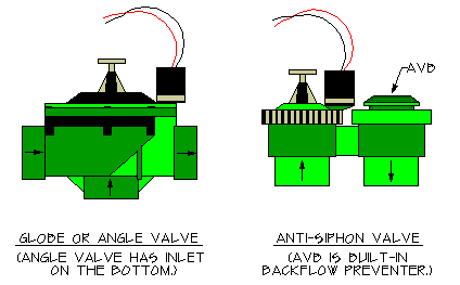
Globe or angle valve:
This valve is available in any size and is commonly installed underground in a box or vault. Since it doesn’t incorporate a backflow preventer you must provide one separately. See the article on backflow preventers. The globe style valve is the most common used valve on commercial and larger size sprinkler systems.
Anti-siphon valve:
Available only in 3/4″ and 1″ size. This is the most common used valve style for homeowners. The anti-siphon valve incorporates a backflow preventer into the valve. This saves a considerable amount of money, as backflow preventers are very expensive. The anti-siphon valve MUST be installed above ground and MUST be at least 6″ higher than the highest sprinkler head. This means that if you want to use anti-siphon valves you will have to locate the valves at the highest point in your yard, and run a water supply pipe to them from the water source (this water supply is called a “mainline”). The mainline pipe leading to the anti-siphon valves should be buried 18″ deep to protect it.
Valve Operation/Control Systems
Manual, Hydraulic and Solenoid Valves:
The sprinkler valves may be manually operated or they can be remotely controlled (automatic valves.) Manual control is simple, the valve has a handle that you use to turn it on and off using your hand as the power source. Remote control valves are either electric or hydraulic operated using a timer or other signaling device to tell them to open and close. Today almost all of sprinkler control valves are electric powered solenoid valves. The electric solenoid valve operates on 24 volt alternating current (vac) and is turned on and off by a timer called an “irrigation controller” or often just “controller”. Anti-siphon, globe, and angle valves styles are all available as automatic valves.
Solenoid Valve and Controller Compatibility
Pretty much all 24 volt valves and controllers are compatible with each other. The most common exception to this rule is valves operated by controllers that are battery or solar powered. (By battery powered I mean they are not plugged into a power source other than the battery. Many controllers have a battery to prevent program loss in case of a power failure, these are not “battery operated”.) So in most cases you can buy a brand “X” controller and it will work fine with brand “Y” valves. You can even mix two or more brands of valves together if for some reason that appealed to you. For example the irrigation system where I test valves and controllers has many different brands all running together. If the valve is not “universal” or compatible it will typically have a warning on the packaging.
Flow Control
I strongly recommend that if you are going to use automatic valves, you select a valve model that has a manual flow adjustment control feature on it. Don’t confuse the flow control with a manual on/off switch. The flow control is a separate handle (sometimes a screw) in addition to the manual on/off control on the valve. This flow control feature is not found on many of the less expensive “budget” valves. The flow control bypasses the automatic valve features allowing the valve to be closed in an emergency by turning a handle just like a standard manual valve. More important is that it also allows the valve to be “throttled”, that is, the water flow may be adjusted to any rate desired. This ability to adjust the flow rate is very useful in many different situations, both when installing your sprinkler system and later when managing it. It can literally make the difference between being able to make a troublesome valve work and having to remove and replace it! I very strongly suggest that this is a feature worth the extra cost.
![]()
- Using the manual flow control you can manually force the valve closed if it sticks open. The manual on/off switch will not close the valve if it is stuck open. Failure to close automatically is one of the most common valve problems, so there’s a good chance that someday you will use the flow control to force closed a valve that is stuck open.
- If your flows are on the low end of the valve’s operation range, it may be helpful to throttle down the flow control to make the valve close faster and more reliably. Without the flow control feature you may have a lot of problems in this situation, you will probably have to replace the valve.
- Partially closing the flow control will make the valve close faster, which is not something you want to do normally, but sometimes it is desirable. On automatic systems it is common for the next valve to open before the previous one fully closes. The resulting loss of pressure due to two valve circuits being on at the same time can cause the first valve to never fully close. A flow control on the valve can help correct this problem.
- Buy valves with the flow control feature. Just do it. Don’t be one of the many people who later makes some lame excuse to me, like “the guy at the store, who normally works in the paint department but was filling in for the day on the irrigation aisle, said it was a waste of money!”
Should You Use Metal or Plastic Valves?
Sprinkler valves come in both brass and plastic models. Most valves used today are plastic, but brass is not out of the picture. There is no doubt that a brass valve will last longer in most situations, especially if installed above ground in the sunlight. From an operational point of view both are reliable, especially for automatic systems. For manual valves my experience is that plastic valves wear out fast and have a very short life. Brass will last much longer. If you use plastic valves above ground you may wish to consider building a cover for them to protect them from sunlight, which can destroy the plastic over time.
Two types of plastic material are used for valves. Glass-reinforced nylon is the best, it is tougher, more resistant to impact, and has a higher pressure rating. PVC is used for lower cost valves, it still is pretty strong, although that really depends on how thick the plastic is! A few valves use ABS plastic or polyethylene, especially for minor parts like screws or caps. Both of these plastics are less strong and are typically used for parts with little stress on them. I recommend avoiding valves with “solvent weld” connections (the pipe glues directly into the valve.) If the valve fails, they can be difficult to replace. Only the cheapest valves come with solvent weld connections. Hmmm… cheap valves fail more and with glued ends are harder to replace- sounds like a bad idea.
Jar Top or Traditional Top Held on with Screws?
OK, just personal opinion here, but I don’t see any advantage to a jar top valve. Yes, they seem to work as well as a top with screws holding it on. They primarily are only found on cheaper valves. The only selling point I have heard for them is that they are supposed to be faster to open for repairs. Are you repairing it that often? I hope not! But I guess if it is a cheap valve…? My experience is that by the time the valve is old enough to need repairs the jar top has seized up and it takes a strap wrench to get the top off. Personally I prefer using a simple screwdriver to remove a few screws as opposed to wrestling with a strap wrench in a tight spot like a valve box.
Maintenance
Today’s valves are pretty maintenance free. Almost all automatic valve failures result from installation or design problems. Ignore the following and you will hate your valves regardless of what type or brand you buy!
![]()
Join the “Hall of Regrets”! Simply ignore the following advice, then send me your “I’m an idiot, I wish I’d listened…” sob story. I’ll add it to my collection and shed an alligator tear or two for you!
- Dirt in the irrigation pipes. Inside the valve there are very small water passages that lead to and from the solenoid. Water must flow freely through these small passages. If a grain of sand or glob of algae gets into these passages it can block them and the valve will fail to open or (more likely) fail to close. It is critical to flush all the dirt out of the pipes before installing the valves. A 100 to 200 mesh filter installed at the water source connection can also help keep out contaminates that come in with the water supply. You may be surprised to learn that most water companies have considerable amounts of sand in their pipes. When you install a new sprinkler system the higher flows stir up this sand and then it gets into your new system. That’s why I suggest to you in the installation tutorial to flush for so long. You have to get the sand out of both the sprinkler system pipes and the water supply pipes! I can’t stress this enough! It’s like a cheap low-flow toilet. You have to flush, flush, and flush again!
- Almost all valve solenoid failures are caused by water getting into the solenoid. The water gets into them through the wires. The solenoid wires have multiple strands of wires twisted together with insulation around them. Because they are twisted there are very small gaps between the wires which form passages along the length of the wire. Water is sucked up through these small passages and deposited into the solenoid by capillary action. Thus it is critically important that the wire splices on the valves be completely water proof so that water can’t be sucked into the solenoid through the wires. You should water-proof the wire splices right after you test the valves! No kidding, a single drop of water on the bare valve wire end can be quickly sucked up into the solenoid and will ruin the solenoid. The Installation Tutorial has more on this.
Valve Size and Pressure Losses:
Emergency Shut-Off Valve:
The pressure loss through the emergency shut-off valve is not significant enough to worry with. We will ignore it. The emergency shut-off valve should be the same size as the pipe it is installed on. If a smaller size shut-off valve is used then you do need to worry about losing pressure through the valve. Probably about 2 PSI would be a safe assumption of the pressure loss.
Automatic Valves:
WARNING!!! If you use the wrong size automatic valve, the valve may not work! READ THAT AGAIN! Let it sink in. The correct valve size often will not be the same size as the pipe it is connected to.
![]()
The pressure loss in an automatic solenoid valve is the primary energy source used by the valve to open and close the valve. The electricity sent to the valve solenoid is just used to jump-start the process, the real force used is the water pressure. If the valve doesn’t have enough pressure loss it will not have the energy needed to close by itself. Always size automatic valves based on the flow rate using the manufacturer’s chart as a guide. Never assume that the valve should be the same size as the pipe! It is very common for the valve to be a different size than the pipe it is installed on. I have seen some rare cases where a 3/4″ valve was the proper size for the flow through a 2″ pipe!!! If you absolutely must guess, use the next solenoid valve size smaller than the pipe size and assume a pressure loss of 6 PSI. Never guess if your flow is less than 5 GPM, always use a chart! Many automatic valves won’t work at all at flows below 5 GPM!
The size of the automatic valves is determined by the manufacturer’s recommended flow range, together with the pressure loss through the valve at the selected flow. You will need to get the valve manufacturer’s flow chart for the model of valve you plan to use. This information should be on the valve packaging. If you can’t find it on the package, try the valve manufacturer’s website or ask for a data sheet on the valve at the store where you buy the valve. (At discount home improvement stores you are likely to get a blank stare from the employee if you ask for a data sheet!)
Some valves don’t appear to have data sheets available anywhere, so as a last resort I’ve assembled some data for you based on my own research for some of the more popular ones. You will find it in the reviews on this website, Click Here. That said, if the valve manufacturer doesn’t provide this necessary information it shows an extreme lack of professionalism, I would be very reluctant to use the product!
If you can’t find pressure loss and flow range information for the valve you want to use, I strongly suggest you use a different brand of valve. After the valve is installed is not a good time to discover it’s the wrong size and won’t open or close automatically!
Example: let’s say you are going to use an automatic anti-siphon type valve. Your Design Flow is 20 GPM, so for now we will assume the flow through the valve will also be 20 GPM. (If it turns out the flow will be less, you can resize the valve later.) The manufacturer’s flow chart would look something like this:
Doesn’t Work Valve Company, Inc. – Valve Performance Data
| 5 GPM | 10 GPM | 15 GPM | 20 GPM | 25 GPM | |
| 3/4″ Anti-Siphon Valve | 5.0 PSI | 5.5 PSI | 6.0 PSI | 8.0 PSI | — |
| 1″ Anti-Siphon Valve | 2.5 PSI | 3.5 PSI | 3.0 PSI | 4.0 PSI | 9.0 PSI |
Warning: The chart above is not real. DO NOT USE THESE VALUES!
The example chart above tells us that the pressure loss for our valve at 20 GPM flow would be 8.0 PSI if we used a 3/4″ valve and 4.0 if we used a 1″ valve. So we could use either one. The pressure loss information from the chart would be the number that you write into your Pressure Loss Table on the “_____ PSI – Valves” line. So if we decided to use the 3/4″ valve, the value would be 8 PSI. But what if after adding all the pressure losses in the loss table, you discover that the losses are too high? In that case you could go back and change to a 1″ valve. That would reduce the pressure loss down to 4 PSI, rather than 8. With that said, as a general rule I try to avoid losing more than 6 PSI through a valve. So I would not use a 3/4″ valve in the example above if it were my sprinkler system. Why? Valves need pressure drop for them to work correctly, but really high pressure losses are hard on the valve. As the pressure loss through an automatic valve increases, the speed with which the valve closes also increases. Thus a high pressure loss can cause the valve to snap closed extremely fast, and that is bad for the entire sprinkler system. Plus the water is moving extremely fast through the valves at those higher pressure loss rates, resulting in more wear on the valve seats. The result is that the valve will fail earlier.
If you looked closely at the chart above you may have noted a couple of interesting items. First, and most obvious, is that no pressure loss is given for a 3/4″ valve at 25 GPM. This is because that flow is outside the acceptable range for the valve. You should not use the valve for that flow. The next item is less obvious, but if you look closely, you will notice the pressure loss for the 1″ size valve is less at the 15 GPM than it is at the lower 10 GPM flow! No, it isn’t a mistake. It is very common for valves to have higher pressure losses at very low flows, so don’t panic if you notice this on a flow chart, it’s not a misprint.
Can a valve be smaller than the pipe it is connected to?
As you move through the tutorial you will find that even though the valve will handle a certain flow, that flow is often too high for the same size of pipe. So it is very common to have a valve that is one, or even two, sizes smaller than the pipe it is installed in. In fact it is so common that they actually make special pipe fittings (connectors) for this. For example they make a PVC plastic male adapter that glues onto 1″ pvc pipe, but has 3/4″ threads to allow you to install a 3/4″ valve on a 1″ PVC pipe. They also make one that glues onto 1 1/4″ pipe but has 1″ threads.
For Manual Valves:
Manual valves are much more forgiving than automatic valves. You don’t need to worry about having enough pressure to allow the valve to close by itself, it uses “elbow grease” to power it! However, you still need to find out what the pressure loss through the valve will be so you can enter it in your Pressure Loss Table. As with the automatic valves, you use a chart provided by the manufacturer for this. Follow the same procedure given above for automatic valves. Unfortunately, pressure loss data for manual valves can be hard to find as many manufacturers don’t provide it. As a general rule, allow 2 PSI pressure loss for a globe or angle type manual control valve, 5 PSI if it is an anti-siphon valve. Manual irrigation control valves should be of the “angle” or “globe” type with replaceable rubber seats. Never use a gate valve as a control valve. Gate valves are not made to be regularly opened and shut. Many gate valves will start leaking after as little as 10 uses!
Want to use a manual valve now but change to an automatic valve later? No problem. Simply design for the automatic valve, but use the manual one instead. Then you can replace it later when you want to automate the system. Another way to do this is to install the automatic valve and simply operate it manually using the manual on/off lever. If you do this, then later you just install a controller as well as wires between the controller and the valves and you have an automatic control system.
This article is part of the Sprinkler Irrigation Design Tutorial
<<< Previous Page ||| Tutorial Index ||| Next Page >>>
By using this tutorial you agree to be bound by the conditions and limitations listed on the Terms of Use page.
Irrigation Mainlines
Quick & Dirty Summary
Definition of irrigation mainline: The mainline is all the pipes between the water source (POC) and the irrigation zone control valves. Another definition is that mainline is any pipe that is always pressurized with water.
Worksheet for Choosing Your Mainline Pipe or Tube
Excessive Water Pressure: In all cases if your static water pressure exceeds 100 PSI it is advisable to install a pressure regulating valve at the irrigation connection point to maintain a pressure lower than 100 PSI. All of these pipes or tubes may burst at higher pressures.
Temperate Areas (ground doesn’t freeze in winter)
- Rocky Soil: Is your ground very rocky, so that it would be impossible to keep rocks larger than 2″ diameter from contacting the pipe? If “yes” consider using PEX tubing for you mainline.
- Normal soil: If ground is not rocky consider using SCH 40 PVC pipe for your mainline. If pipe larger than 2″ is needed use Cl 315 PVC pipe.
Frost Areas (ground freezes at least a couple inches deep in winter.)
- If your static water pressure is less than 60 PSI the use of 125 PSI rated poly tube may be sufficient if cost is a major issue. However it would be better to use 160 PSI tube if you can afford it.
- For static water pressure between 60 and 80 PSI, use 160 PSI rated poly tube.
- For static water pressure between 80 and 100 PSI, use 200 PSI rated poly tube.
- Make sure you provide a method to blow out or drain the water from the mainline completely during winter.
Pipe or Tube Size: There is no easy way to say what exact size you should use. If you really don’t want to do calculations the following is a very rough educated guess that will work for most (but not all) situations. Use a pipe or tube size that is the next size larger than the water supply pipe the irrigation system (POC) is tapped into. Do not use smaller than 3/4″. Ie; if the irrigation system mainline is going to tap into a 1″ house water supply pipe (POC), then use a 1 1/4″ size mainline for the irrigation.
Pipe Depth: Bury the mainline pipe at least 18″ deep from the top of the pipe to the ground surface. It is critical that this pipe be protected from accidental damage and light frosts.
No water running through the house! To avoid nasty surprises, avoid using a water supply (POC) for your irrigation system that passes through a house inside the walls, under floors, or through the attic.
Keep reading for in-depth details and answers to “why?”
How to Find Your GPM & PSI – Municipal Water Source
If your water comes to you from a water company, you’re on the right page.
However…
If your water supply is from a pump and/or well on your property, skip this page and go to How to Measure the GPM & PSI from a Pump or Well page. If your water comes from a tank or other gravity fed system, skip this page and go to How to Measure the GPM & PSI from a Gravity Fed Water System.
![]()
If you have a printer, there is a Sprinkler System Design Data Form that will make things easier for you. There is also a PDF version of the Sprinkler System Design Data Form.
The path ahead viewed dimly through the fog??? What we’re about to embark on here is known as “doing it the right way”. We are going to start by figuring out what the maximum water supply would be if you had perfect conditions, such as a very short pipe from the water meter to your house, lots of water pressure, a small yard, a happy family, a low interest rate mortgage, and good neighbors! Then we are going to modify that number later in the tutorial to reflect your actual conditions (long pipe, lousy water pressure, bad neighbors, whatever.)
The end result is that we will determine what the exact, optimum water supply is for designing your sprinkler system. What that means for you is that your sprinkler system will use less water, last longer, and there won’t be dry spots! Now it’s going to be a little more work than “guesstimating” would be, but it will be worth it. Don’t get discouraged, be patient, and it will all come together. The worst thing you could do right now is to try deciding what sprinkler you want to use. That would be “putting the cart before the horse”. Trust me, I know what I’m doing. Now let’s get on with it…
A. Find your water supply pipe.
Hopefully you already know where the water service pipe comes onto your property, or at least where it enters your house.
Mild Winter Climates: In milder climate areas there is typically a shut-off valve and or a water meter at the location where the pipe enters the property. From there the pipe generally goes to the house, then surfaces above ground where a house shut-off valve is located, then the pipe turns and runs into the side of the house. Often this location where the pipe enters the house is where the tap for the irrigation system will be made.
Note the “W” etched in the curb in front of the concrete water meter box in the photo above. Often there will be some type of mark on a curb at the location that the water supply pipe to the house runs under it.
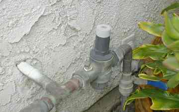
The photo above is of a typical mild-climate water supply line where it enters the house. This one has a rather unusual model of pressure regulator (the gizmo with the white adjustment knob on top) to reduce the water pressure. Many houses do not have a pressure regulator. A ball valve (with a blue handle, the handle is in the “off” position) is on the incoming water supply pipe. The pipe going into the wall is the house supply. The pipe exiting the photo at the lower left goes to a hose bib.
Cold Winter Climates: In colder climates the water line often enters directly into the basement or crawl space under the house from underground. This water pipe to the house is often buried very deep to keep it below the frost line. The shut-off valve, and possibly a water meter, are often located in the basement or crawl space to help protect them from freezing.
The photo above shows a typical water supply line in a cold-winter climate. A copper water pipe enters through floor, goes up into a ball valve (yellow handle), then through a pressure regulator, then a remote-reading water meter. You would tap in for the sprinklers after the water meter. The mainline supply size would be measured on the copper pipe coming out of the floor. The water pressure in this case could be measured at any water faucet after the regulator (probably any faucet in the whole house would work). Photo credit and thanks to Ed Pletsch.
What type of pipe is it?
Once you find your supply pipe you need to know what type of pipe or tubing it is. Keep in mind that there may be more than one type of pipe or tubing used at different locations! Often copper is used under concrete slabs and then it converts to PEX for other locations.
Steel Pipe. Steel pipe comes in two types, black steel (used mostly for gas lines) and galvanized steel (galv. steel) which is used for water pipes. Galvanized steel pipe will be a silver gray color, and a magnet will stick to it. It will have threaded joints. Steel pipe is made in conformance with IPS (iron pipe size) standards. Galvanized pipe is often found on homes in inland areas, especially on less expensive tract homes.
Brass Pipe. Brass pipe is sometimes used for homes. Like copper it can take on a greenish tint with age. A magnet will not stick to it. It will have threaded joints. Brass pipe is made in made in conformance with IPS (iron pipe size) standards. Brass is not very common except for short sections of pipe, due to cost.
PVC Pipe. PVC plastic pipe is almost always white or gray, and is more rigid than the other commonly used types of plastic water pipe. Standard PVC pipe is made in conformance with IPS (iron pipe size) standards. It should have the letters “PVC” printed on the pipe. PVC is fairly rigid, and it is not easily scratched with your fingernail. PVC tends to be more commonly used in mild climate areas. Another type of PVC called CPVC is sometimes used inside homes and often is found in older mobile homes. It is similar to regular PVC, but will be labeled “CPVC”. Most often it is a yellowish, gold, or tan color. CPVC in homes is usually made to copper tube sizes (look for “SDR-11” printed on the pipe), but is also sometimes iron pipe size (labeled IPS). PVC is often used for house supply pipes in mild winter areas.
Copper Tube. Copper tube is very common in homes. It takes on a dirty green color as it ages. A magnet will not stick to it. Most joints will be soldered, look for silver color solder at the joints to identify it. Copper tube has a different diameter than iron pipes, and is made in sizes known as CTS (copper tube size). Copper has been the standard “high quality” tube used on better homes for decades. Often used in areas near the coast where salt air causes rapid corrosion of steel.
PEX and PE Tube. Both are both polyethylene (poly) products. Both tend to be used in areas with severe winters and/or rocky soil. There is a lot of confusion over these two poly-based products. Be careful, both are sometimes called “poly”, especially by the sales people in the big home improvement stores. True PEX is a stronger form of cross-linked polyethylene that has become popular in recent years. Both PEX and PE are flexible, and both have a glossy appearance and slick surface. So how do you tell which one you have? Older PE is almost always black, and in most cases PEX is not black. PE is almost never used inside a house if the house was built to code. The surest thing to look for are the letters “PEX” printed on the tubing. Making things even worse, white PEX looks a lot like PVC, especially if it is old or dirty! PEX is easily scratched with a fingernail, PVC scratches, but not easily. PEX was not invented until the ’70s, and it is seldom found in homes built before 1975. (It wasn’t officially sold in the USA until 1985. Of course, if your house has been remodeled, you could still have it in a older house.) PEX is almost always made to conform with CTS sizes. The heavy duty PE tube used for plumbing is most often made to a uniform size standard (labeled “SDR-7”), but many different PE products used for irrigation do not conform with this size standard. Be careful when working with PE tube, if possible take a sample with you when you go shopping for parts so you can test fit them at the store. PEX is quickly becoming the default tube for piping new homes due to low cost and ease of installation.
Warning: PEX pipe has a very thick wall, thus it has a smaller inside area for the water to flow through. This means it has much higher pressure losses when the water passes through it. For this reason you need to be careful when replacing a copper or PE tube with a PEX tube. Often when replacing a copper or PE tube with a PEX tube it is necessary to use PEX that is one size larger than the tube it is replacing. So if you are replacing a 3/4″ copper tube with PEX, you should consider using 1″ size PEX tube for the replacement. Otherwise you may notice a drop in water pressure after the replacement is made.
![]() One good hint to the type of pipe is the way the pipes are connected to each other. PEX and PE are never glued at the joints. Sometimes PEX & PE are heat welded together, but most of the time they are connected together with fittings using clamps, teeth, or compression-nuts that hold the tube onto or into the fitting. (“Fittings” is the term we use for the various connectors that are used to join two or more pipes together.) If the pipe has glued joints it is almost always going to be PVC or ABS. (ABS plastic is typically black rigid pipe, almost always 3″ or larger in diameter, and is mostly used for sewer and drainage pipes. ABS can be other colors so don’t assume a pipe is PVC just because it is white or gray!) Another hint is that poly pipe tends to be used in colder climates, and PVC tends to be used in warmer climates. If you have to regularly shovel snow from the driveway, chances are the pipe is PE or PEX. Copper pipe is often soldered to the fittings. Look for the silver color solder at joints. Steel and brass pipe have threaded connections, a few threads almost always are visible at the joints. Confused yet? Your best bet is to find lettering on the pipe that says what type it is.
One good hint to the type of pipe is the way the pipes are connected to each other. PEX and PE are never glued at the joints. Sometimes PEX & PE are heat welded together, but most of the time they are connected together with fittings using clamps, teeth, or compression-nuts that hold the tube onto or into the fitting. (“Fittings” is the term we use for the various connectors that are used to join two or more pipes together.) If the pipe has glued joints it is almost always going to be PVC or ABS. (ABS plastic is typically black rigid pipe, almost always 3″ or larger in diameter, and is mostly used for sewer and drainage pipes. ABS can be other colors so don’t assume a pipe is PVC just because it is white or gray!) Another hint is that poly pipe tends to be used in colder climates, and PVC tends to be used in warmer climates. If you have to regularly shovel snow from the driveway, chances are the pipe is PE or PEX. Copper pipe is often soldered to the fittings. Look for the silver color solder at joints. Steel and brass pipe have threaded connections, a few threads almost always are visible at the joints. Confused yet? Your best bet is to find lettering on the pipe that says what type it is.
B. Find your Water Meter:
Now we need to know if you have a water meter. Most, but not all, water companies use a water meter to measure the amount of water you use. If you don’t have a meter, there will almost always be a shut-off valve at the point your house water line connects to the water provider’s pipes. Often the valves are buried, sometimes several feet down, and a sleeve comes up to the surface with a small lid or box over it. The water company uses a special tool that can reach down and open or close the valve. Often grass has completely grown over the lid and you can’t find it. Try probing the ground with a pitchfork, metal rake, or screwdriver to find the hard cover of the box.
The water meters are normally installed in an underground box as close as possible to the property line. This is usually at the street or alley. Most of the time the box will have “water meter” or the water company name stamped on the lid. In areas with severely cold winters the water meter is often installed in the house basement or a utility room of the house. If you still can’t find it, call your water company and request their assistance.
Try to find a size stamped on the meter. If you can’t find a size, ask your water company or just assume the meter is the next size SMALLER than the pipe running to the house. It is common for the meter to be one size smaller than the pipe. Standard water meter sizes are: 5/8″, 3/4″, 1″, 1 1/2″.
Spiders and snakes: If the meter is in a box, watch out for spiders and ants in the meter box! Most of the “pro” irrigation repair guys I know carry a can of spider spray with them! Sometimes we find snakes, rats, gophers, and other beasts in the boxes too! I found a turtle shell in a box once. No tunnels or holes into the box that I could find. I have no idea how it got in there.
![]() Enter the meter size on your Design Data Form. If you don’t have a meter, enter 0 (zero).
Enter the meter size on your Design Data Form. If you don’t have a meter, enter 0 (zero).
C. Measure Your Water Pressure
Water pressure is the energy that powers your sprinkler system, so it is very important. If you work with it, it will make your sprinklers do the “rain dance”. If you ignore it, it can bite you hard in the wallet! For this tutorial I use the pressure units “PSI” which means “pounds per square inch”. When pros talk about pressure readings we almost never say the words “pounds per square inch”, we just say the letter names “P. S. I”. Outside of the United States pressure is most often measured in “bars”.
First off, grab the phone and call up your water supplier. Ask them for the “static water pressure” for your neighborhood. Don’t be shy, people call them all the time to ask! They may give you a pressure range, like 40-60 PSI. If so, write down the LOW number of this range. You can also measure your own water pressure using a pressure gauge that attaches to a hose bib on your house (you can purchase a 0-120 PSI gauge with a hose adapter on it at pretty much any hardware store).
Pressure regulators (also called pressure reducing valves)
Pressure regulators are devices used to reduce the water pressure and are commonly found on home water supplies in towns with hills. It takes lots of water pressure to lift water uphill. So in order to get the water to the houses on top of the hill the water pressure in the water system has to be very high. But this causes the pressure at the homes at the bottom of the hill to be too high. So pressure regulators are installed on the water supply pipes to homes in the lower areas of town, where the pressures are very high. The pressure regulators are generally set to someplace between 50 and 65 PSI.
If the water company tells you your neighborhood pressure is over 65 PSI, you probably have a pressure regulator installed someplace on the water supply line to the house. The pressure regulator reduces the water pressure in your house, so that it doesn’t damage your plumbing fixtures. Look around and see if you can find it (see the pressure regulators in the pictures above). The regulator may be installed near the water meter or at the point where the water supply pipe enters the house. This is important, because if you have a regulator and you tap into the water supply for your sprinklers after the regulator, the pressure will be a lot lower.
If you have a pressure regulator on your house you must use a gauge to test the water pressure yourself. Most pressure regulators are adjustable, so the water company has no idea what pressure the regulator is set at. When in doubt, test the water pressure with a gauge.
At this point you should make at least a preliminary decision as to where you want to tap into the house water supply pipe for the irrigation system water. Typically, the closer you can tap to the point the water enters your property, the better. Of course, you must tap into the pipe after the water meter. In areas where it gets very cold some people like to tap into a pipe in the basement or someplace else inside a heated building. That way they don’t have to worry about the shut-off valve for the irrigation freezing. (Be sure to install a drain valve after the shut-off valve to drain the water out of the irrigation pipe during freezing weather!) If you have a pressure regulator, consider if it would be better to tap before or after it.
A static water pressure higher than 70 PSI can damage the fixtures and appliances in a household. If you measure a static water pressure higher than 70 PSI when you do your water pressure check as described below, then you should consider installing a pressure regulator on your house water supply if there is not one already. It will help your faucets, pipes, washing machine, dish washer, etc. to all last a lot longer. Make sure it is a good quality brass-body pressure regulator.
![]() For a pressure regulator to work accurately the pressure setting on it must be at least 15 PSI lower than the inlet pressure. So if your static pressure is 70 PSI, the highest pressure you should set on the pressure regulator would be 55 PSI. 55 PSI is a good pressure for both the needs of a house and a sprinkler system.
For a pressure regulator to work accurately the pressure setting on it must be at least 15 PSI lower than the inlet pressure. So if your static pressure is 70 PSI, the highest pressure you should set on the pressure regulator would be 55 PSI. 55 PSI is a good pressure for both the needs of a house and a sprinkler system.
Hose Bibs as a Water Supply Source = BAD!
Using a hose bib or even a “sprinkler system stub-out pipe” provided on the side of the house for sprinklers is not a good idea. There are often unknown restrictions in the house piping that cause the water supply from these hose bibs to be severely limited. The water running through the house pipes can also be very noisy at night and disturbs some people’s sleep. Do this only as a last resort, when there is no other reasonable way to get water for your sprinkler system. I would suggest you assume the pipe is 1/2″ size, even if it appears larger. If you have concrete that prevents running a new pipe around the house, call a boring contractor and find out how much it would cost to bore a 1″ pipe under the concrete. It may be worth the price. Directional boring technology now allows them to bore and install curved pipes around obstacles.
How to Measure the Water Pressure with a Gauge
![]()
Important: If you want to test the pressure yourself, everything that uses water in your home: faucets, ice makers, toilets, etc., MUST be turned off when you take the measurement (that’s why its called “static” water pressure, the water isn’t moving.) Everything! This is critical or you will get a false low reading! You can test the pressure at any faucet that is at about the same height as the proposed irrigation tap. If all the water is turned off, the pressure will be exactly the same regardless of where you test it. (Try it and see!) The easiest place to test the pressure is usually a hose bib or garden valve on the outside wall of the house.
To test the water pressure using a gauge, attach the gauge to a water outlet, like a hose bib or washing machine connection. The place where you attach the gauge can be anywhere in the house, as long as it is about the same height (elevation) as the place where you will tap in the sprinkler system supply. Ie; don’t check it on the 3rd floor if you plan to attach the sprinklers at the first floor! (It is one of those weird, hard to understand hydraulic laws that as long as the water is not flowing the pressure is the same at any point on a pipe that has the same elevation above sea level.) Double check that all the water so water is turned off and not flowing in the house pipes. Then turn on the valve the gauge is connected to and allow the water to enter the gauge. Read the pressure on the gauge. That’s all there is to it, it’s very easy to do! Turn off the water and disconnect the gauge, you’re done!
OK, I realize I may have confused you, because earlier I told you not to use a hose bib to tap the sprinklers into, and now I just told you that you can use a hose bib to measure the static pressure. This is because you can get an accurate pressure measurement from a hose bib– if the water is not flowing, as described. The small pipe can’t restrict the flow if the water isn’t flowing! Confused? Hydraulics is hard to understand. I may sound crazy but I know what I’m doing! Often users of the tutorial have an “ah ha!” moment when they get about 95% done with their first design and suddenly it all makes sense.
![]()
The static water pressure that you were given (or you measured with a gauge) is your Design Pressure. Write down the “Design Pressure” on your Design Data Form!
D. Measure the Maximum Available Flow (GPM)
Flow is the traveling companion of water pressure. Pressure is the “energy” that moves the water through the pipes. Flow is the measure of how much water is moved in a given amount of time. Flow is measured in this tutorial using Gallons per Minute (GPM). Other common units used to measure flow include cubic feet per second (commonly used to measure river flows here in the USA), liters per minute, cubic meters per hour, and many others. Now that you know your Design Pressure you need to determine how much water you can use at a time, or your available flow.
Measure Your Supply Pipe Size
You need to find the water supply pipe and measure it’s size. Grab a piece of string about 6″(152mm) long, then find the location where your water supply pipe enters the house. Strip away any insulation, so you can get at the pipe and wrap the string around it. Measure how many inches of string it takes to go around the pipe once.
The string length is the circumference of the pipe (yikes, bad memories of high school geometry!). Using the circumference we can calculate the diameter of the pipe, which allows us to look up the pipe size, from which we can calculate the flow of water using the formula… zzzzzzzzzz….. Let’s forget all those calculations! Based on the string length use the table below to find your pipe size.
For Copper Pipe & PEX Tube
2.75″ (70mm) = 3/4″ pipe
3.53″ (90mm) = 1″ pipe
4.32″ (110mm) = 1¼” pipe
5.10″ (130mm) = 1½” pipe
For Steel, Brass or PVC Plastic Pipe
3.25″ (83mm) = 3/4″ pipe
4.00″(102mm) = 1″ pipe
5.00″(127mm) = 1¼” pipe
6.00″(152mm) = 1½” pipe
For most PE Tube
2.96-3.33″ (75-85mm) = 3/4″ pipe
3.74-4.24″ (95-108mm) = 1″ pipe
4.90-5.57″ (124-141mm) = 1¼” pipe
5.70-6.28″ (145-160mm) = 1½” pipe
Your string length will vary a little, depending on such unavoidable variables as string stretch, dirt on pipe, manufacturing tolerance, what kind of mood you’re in, etc.
![]()
Enter the supply pipe size on your Design Data Form! Also make a note of the type– copper, brass, steel, PVC, PEX, or PE.
Find Your Maximum Available GPM:
Your maximum available GPM is the maximum flow of water you have available for your sprinkler system. Actually, it would be more accurate to call this the Maximum Safe GPM. In most cases it is possible to push a higher flow (GPM) through the pipe. However, at high flows the water actually damages the inside of the pipe.
Use the smallest pipe to determine the Maximum Available Flow. Often the water supply coming into your property will not be a single type and size of pipe. You may have a plastic pipe running underground from the water company to your house. When the pipe enters the house it might switch from plastic to copper pipe, or possibly it might be galvanized steel. Then as the water supply pipe runs through the house it likely branches off in several directions with the pipe becoming smaller and smaller in size as it goes. When determining your Maximum Available GPM you will need to check the Maximum Available Flow for each of the types of pipe that the water will pass through, then use the lowest value as the Maximum Available GPM for your sprinkler design. You only need to be concerned about the pipes the water will pass through before it reaches the point where you are going to tap into it for the irrigation system.
There is an exception to the statement above. Often a short section of a smaller pipe size will be present on the water supply for one reason or another. Maybe the plumber didn’t want to drill a larger hole in the wall for the pipe. As long as this smaller pipe section is less than 5 feet long, you can ignore it and use the larger pipe size to determine maximum flow. The higher flow will be able to squeeze through the smaller pipe. The smaller pipe may wear out faster over time, but typically these short pipes are in places where they are easy to replace. Plus, the smaller pipe is often brass or steel, which has a higher resistance to wear than copper or plastic. You have to make a judgement call on this. In most cases I choose to ignore the small section of pipe.
Small Valves. It is not uncommon to find that a shut-off valve installed on the water supply pipe is a smaller size than the pipe. Don’t worry about it. It will not impact the available flow and valves are constructed to handle higher flows than the pipe.
Example 1: You find the water supply pipe entering the house, examine and measure it, and find that it is 1″ copper pipe. But you’re an ambitious type, so you also have done some digging around in the yard and discovered that the pipe going to the house through the yard is 1 1/4″ PE plastic. It just changes to copper about 6 feet away from the house (this is actually a fairly common situation.) After the copper pipe enters the house it quickly branches off in multiple directions and becomes smaller, but this doesn’t matter to you, because you have already decided that you are going to tap your irrigation system into the 1″ copper pipe right where it enters the house. So the irrigation water will not pass through any of those smaller pipes inside the house and you can ignore them.
Looking at the table you find that 1 1/4″ PE gives a flow of 23 GPM. But looking at 1″ copper pipe in the table shows a flow of only 18 GPM. Since the copper pipe is over 5 feet long you can’t just ignore it. This means you must use the lower 18 GPM value. But wait a minute! What if instead of tapping into the copper pipe, you decide to tap into the PE pipe out in the yard before it switches to copper? Now you can use the higher 23 GPM value because the water will no longer go through the 1″ copper pipe!
Example 2: You found you have a 3/4″ copper pipe that comes into the basement but you have no idea where or what type of pipe is used in the yard. It’s 0 degrees outside, and you couldn’t get a shovel into the frozen ground even if you wanted to, which you don’t! In this case it’s reasonably safe to assume the pipe in the yard is 3/4″ copper also. So you would use 11 GPM from the table.
Example 3: You have no idea where the water pipe enters the house, you have no idea where it is in the yard, and you have no desire to try to find out. In this case you must face reality, it’s time to hire a sprinkler contractor!
Maximum Available GPM Table (Maximum Safe GPM)
| Maximum Available GPM (Maximum Safe GPM) | |||||
| Pipe Size | Steel Pipe | Copper Pipe | PVC Pipe | PE (poly) Tube | PEX (CTS) Tube |
| 1/2″ | 6 GPM(7 ft/sec) | 6 GPM(7 ft/sec) | 6 GPM(7 ft/sec) | 6 GPM(7 ft/sec) | 3 GPM(7 ft/sec*) |
| 3/4″ | 11 GPM(7 ft/sec) | 11 GPM(7 ft/sec) | 11 GPM(7 ft/sec) | 11 GPM(7 ft/sec) | 7 GPM(7 ft/sec*) |
| 1″ | 18 GPM(7 ft/sec) | 18 GPM(7 ft/sec) | 18 GPM(7 ft/sec) | 18 GPM(7 ft/sec) | 12 GPM(7 ft/sec*) |
| 1 1/4″ | 23 GPM(5 ft/sec) | 23 GPM(5 ft/sec) | 23 GPM(5 ft/sec) | 23 GPM(5 ft/sec) | – |
| 1 1/2″ | 32 GPM(5 ft/sec) | 32 GPM(5 ft/sec) | 32 GPM(5 ft/sec) | 32 GPM(5 ft/sec) | – |
| 2″ | 52 GPM(5 ft/sec) | 52 GPM(5 ft/sec) | 52 GPM(5 ft/sec) | 52 GPM(5 ft/sec) | – |
Important Notes:
- CTS = Copper tubing size.
- Caution: The values in the table above are the maximum safe flows for the given size and type of pipe.
- These values are NOT the amount of flow you actually will use for your sprinkler system! Step #2 will show you how to modify these values to reflect your actual flow.
- Velocities (ft/sec) are shown for reference only.
- * PEX tube has an extremely small inside diameter when compared with the other pipe/tube types, this limits flow. Some manufacturers suggest that PEX will not be damaged by higher flows, up to 10 ft/sec. I don’t feel there is sufficient evidence yet to warrant damaging your plumbing by using flows that are too high, so I am sticking with the old industry standard for plastic pipe of 7 ft/sec maximum velocity. If you wish to take the chance, values at 10 ft/sec are
1/2″=6 GPM, 3/4″=11 GPM and 1″=18 GPM. Use these higher values at your own risk. They could cause serious damage to your both your house plumbing & irrigation piping. Read More on Water Hammer.
Flow Test
A flow test is optional, but suggested if you are not positive about the size or type of water supply pipe. The flow test should be run at a faucet as close as possible to the point you will tap into the water pipe for your irrigation system.
Get a 5-gallon bucket. Old paint buckets work great. Since most 5-gallon buckets actually hold more than 5 gallons of water, you will need to calibrate the bucket as follows: Find an accurate measuring container, and measure out 5 gallons of water into your bucket. Then mark the water level on the side of the bucket with a marking pen so you can easily see it. ?The test is simple. Put the bucket under your water outlet pipe and time how long it takes to fill the bucket to 5 gallons. The formula for calculating the flow in GPM is: 300 divided by the seconds it takes to fill a 5 gallon bucket = GPM.
If the result of the bucket test is lower than the Maximum Available GPM from the table above, something is restricting the flow. It may be the faucet you are using for the test, or there may be a restriction someplace in the house water supply pipe. You can try to find the restriction and get rid of it, or you can simply use the lower flow test GPM for your Initial Design Flow below.
![]()
If the result of the bucket test is higher than the Maximum Available GPM you determined in the table above, use the lower value from the table. The Maximum Available GPM Table gives you the maximum SAFE flow. The bucket test is only used to determine if there is an unseen restriction in the water supply pipe that reduces the flow below the level given in the table. Yes, many sprinkler tutorials and sprinkler salespersons may tell you a bucket test should be used for the design flow, they are wrong! In most cases a bucket test like this one gives you an unsafe flow. See the answers to common questions at the bottom of this page for details on why this happens.
![]()
Enter your Maximum Available GPM on your Design Data Form.
E. Initial Design Flow
Your Design Flow is the maximum amount of water you will design your sprinkler system to use. For now, use the same number as the Maximum Available GPM, or use the actual Flow Test GPM, whichever is lower.
You will probably need to reduce your Design Flow later, so additional lines are provided for Adjusted Design Flows on the Design Data Form. The initial flows here are very optimistic, 20 to 30% too high for most situations. You will make the adjustment, if needed, later in step #2. Don’t worry about it now. This is just an advanced warning so you won’t be surprised when you need to change the flow later.
![]()
Enter your Design Flow on your Design Data Form. Use a pencil so you can change it later!!!!
F. Do you have enough water available?
You are going to need about 20 GPM of water to irrigate 1 acre of grass with sprinklers. One acre is equal to 43,560 square feet (or 4047 square meters). So if you have a 2 acre grass yard you will need to have 40 GPM of water available in order to water it. If you have shrubs, they typically only use 1/2 as much water as grass, so 20 GPM would water 2 acres of shrubs.
![]()
There are only so many hours in the day to water. The amount of water needed varies with the climate, these values are typical for hot summer areas where most sprinkler systems are installed (daily high temperatures over 90 degrees F., 32 degrees C.) These values assume you would be willing to water as many as 10 hours per day. If you are willing to water more hours per day you can increase the area irrigated by a similar percentage.
If you don’t have enough water I can suggest a few ideas for you to look into.
- You can consider pushing the limits and using a higher Minimum available GPM than I recommend in the table above. If you want to try using a higher flow than recommended above, then go to https://irrigationtutorials.com/faq/increase-irrigation-gpm.htm for full instructions on how to proceed.
- Another option is to use drip irrigation for shrub areas. With drip irrigation you only water the area the plant foliage actually covers. Therefore, if the plants only cover half the actual ground area, you only need half the water.
- Consider reducing the amount of lawn and replacing it with shrubs. Shrubs use about half the amount of water as lawn.
- Another option for getting a higher flow is to install a larger water supply pipe. A description of how to do that is at the bottom of this page.
If you’re happy with your Maximum Available GPM value, you can skip down to the end of this page.
Answers to common questions:
![]()
Why is the flow you measured with a bucket often too high? The GPM rates in the Maximum Available GPM Table above are based on a SAFE water velocity. When you do the bucket test, there are few restrictions on the flow, so the water velocity may easily exceed that safe limit. If you design your sprinkler system to exceed these flows some really bad things can happen. The first of these is called “water hammer”. Water hammer is a pressure surge which declares its presence by destroying the weakest point in your plumbing. The weakest point is usually that little water tube that runs between the shut off valve and the toilet in your bathroom, or possibly the ones that go to the sink faucets. The result is a flooded house, and that’s something you don’t need. Water hammer is exponentially related to water pressure. The higher the water pressure, the greater the water hammer danger. If your water pressure is over 80 PSI, I suggest that you reduce your maximum flow found in the table above by 20% and read carefully the High Pressure Alert below! The other bad thing that happens at high flows is called “scrubbing”. Scrubbing is what happens when the high water velocity actually scrubs molecules loose from the inside of the pipe. Eventually it wears away enough that the pipe develops a leak. The higher the velocity, the more scrubbing you get. A little scrubbing may take 20-30 years to create a leak. With a higher velocity the problem becomes much worse. I have seen 7 year old homes need a total replacement of all the copper pipes due to scrubbing damage. This is extremely expensive to repair! In my 30-year-old neighborhood, most of the homes have now had to replace the water supply pipes to the house due to scrubbing damage caused by sprinkler systems installed back in the bad old days before any of us realized the dangers of high flows. There are still a lot of old tutorials and literature being published that were written before the dangers of high flows were discovered, so be careful when comparing advice on this topic. A lot of industry professionals still haven’t gotten the word on this either!
But, but, but… you didn’t hear any water hammer when you did the bucket test, and nothing broke, so what’s the deal? After all, that higher flow could save some serious money on sprinkler parts! The deal is that you are only human. You can’t close the valve fast enough by hand to create water hammer, but don’t worry, an automatic sprinkler valve can! It can snap that valve closed almost instantly. The higher the water pressure, the faster the valve closes. When that valve snaps closed, it sends a shock wave through the pipe (water hammer). It may take weeks or even years for it to wear down the weak point in your plumbing and break, but it will! Then the cost savings on sprinkler parts will seem trivial. Do it right the first time! Water hammer and scrubbing are insidious and relentless. They just keep working away, little by little, day after day. Clunk, clunk, clunk, chew, chew… until the day you come home to a flooded house.
![]()
Clunk, clunk, clunk? Pipe noise!!! I hear those loud noises every time the washing machine or dishwasher runs! Is that water hammer??? You bet it is, and you better do something about it! First, if the water pressure in your house is over 65 PSI, install a pressure regulator to lower the pressure. If that doesn’t get rid of it, go down to your local hardware store and buy a water hammer arrestor. You can get one that screws onto the washing machine or dishwasher fill pipe. They cost about $10-15 and they work pretty well for water hammer caused by appliances. They don’t work nearly as well for water hammer caused by sprinkler systems. This is because many sprinkler systems exceed the maximum water velocities by so much that the arrestor is over-whelmed by it. I’ve written a whole tutorial on this topic: Water Hammer and Air in Pipes.
This article is part of the Sprinkler Design Tutorial Series
<<< Previous Page ||| Tutorial Index ||| Next Page >>>
By using this tutorial you agree to be bound by the conditions and limitations listed on the Terms of Use page.
Sprinkler System Lateral Pipes
Quick & Dirty Summary*
- “Laterals” are what we call the pipes or tubes that are located between your on/off valve and the sprinkler heads. For example, if you are using automatic solenoid valves the pipes between the valves and the sprinkler heads would be called “laterals” or “lateral pipes” or “lateral tubes,” etc.. Because the water is only pressurized in these pipes when the sprinklers are turned on they don’t need as much strength, so the laterals generally use a lower quality pipe to save money.
- In temperate zones it is typical to use Cl 200 PVC pipe for laterals. PVC pipe holds up well to frequent use of the irrigation system and higher water pressures typical of the temperate Zones of the USA. Polyethylene is becoming increasingly popular in temperate zones also, due to increased marketing and ease of installation, but there are still some questions as to how well poly will hold up to the more frequent irrigations and higher water pressures common in these climates.
- In cold winter areas it is typical to use 80 or 100 PSI polyethylene “irrigation” tube for laterals as poly holds up to freezes better than PVC. Consider using a higher 160 PSI pressure rated poly tube if the static water pressure is higher than 60 PSI.
- As water moves through a pipe or tube it loses pressure due to friction. The allowable pressure loss in the laterals is typically kept under 4 PSI, with 6 being the maximum advisable if you have a high static water pressure, or economy is more important than quality. Higher pressure loss can cause poor uniformity of water coverage and lead to “dry spots.”
- Lateral pipes should be buried at least 10″ deep to protect them from damage from lawn aerators and cars driving over them.
*Quick & Dirty Summary information is based on Industry Standards for a typical home irrigation system and will not work for everyone, everywhere. The typical solutions in the Quick & Dirty Summary may not give you the least expensive or most efficient irrigation system. If you want excellent water savings, lowest cost for top quality, or in-depth explanations please keep reading... Continue reading Sprinkler System Lateral Pipes
Fertigation
Automatic fertilizer injectors are the popular gimmick of the moment. I really don’t find them all that convenient, it seems just as easy to spray fertilizer with a sprayer and be able to put it where I want it as it is to calibrate the fertilizer injector. With that said, it seems everyone wants a fertilizer injector lately for some reason.
I’m not a huge fan of fertilizer injectors, especially for sprinkler systems. For drip systems it makes more sense, as the fertilizer water is not sprayed into the air. I think fertilizer injectors are excellent for agricultural crops, but not nearly as well suited for home landscapes. A few of the issues:
1. First is control, the fertilizer gets applied at the same rate to everything. Different plants need different amounts of fertilizer.
2. Second is uniformity, if the fertilizer isn’t evenly mixed into the water you can get burning of foliage. The maker of the fertilizer injector will have recommendations for addressing this issue. Generally it just means you need to have several feet of pipe between the injector and the first sprinkler head or drip emitter.
3. Third is health, most sprinklers produce mist which drifts easily to adjacent property. Without care it can contaminate or cause sickness. The EPA has strict rules regulating maximum wind speed that can occur during chemical applications using aerial spray nozzles. Generally what this boils down to is that the fertilizer injection should be manually controlled and only used when someone is supervising the system.
4. Backflow prevention- because the fertilizers are chemical injection (high hazard) a reduced pressure backflow preventer is technically the only type of backflow preventer that is satisfactory. They are very expensive and few homeowners have them. Talk to your water provider about the specific requirements for your area.
5. Runoff- most residential sprinkler systems have substantial runoff. With fertilizer in the water this can cause environmental problems with storm-water drainage disposal. This high nutrient content runoff water causes algae blooms in lakes and estuaries, and also encourages growth of non-native weed species along streams and rivers.
6. If the fertilizer sprays onto a car it must be washed off immediately. If it drifts onto your neighbors car and sits all night the fertilizer can damage the paint.
7. Nitrogen, the primary nutrient you will be applying, is easily volatilized (evaporated) into the air. This means that when you spray fertilizer as a liquid into the air you loose some of the nitrogen. Two factors heavily influence this. Volatilization is a much greater problem with warmer temperatures and it also increases if the water droplets are smaller.
If you can address all the above issues, then it is a great thing. In agricultural situations with a single crop and strict supervision this is efficient and easy. Homeowners tend to be looking at fertilizer injectors as a “set it and forget it” solution. It is not. It requires much more work than either broadcast or hand applied foliar fertilization methods. Very few commercial landscapers use injectors, high costs and labor requirements for supervision, combined with liability exposure for poisoning pets and people are the reason.
I prefer hand applied foliar treatments where the level of control is much higher. Only the plants that need more fertilizer get it. I am a big fan of foliar applied fertilizer using a sprayer. It is much more efficient than broadcast fertilizer, works faster, and typically results in less environmental pollution.
Tips for Hiring an Irrigation Installer or Contractor
The best tip I have for hiring a contractor is for you to provide the plan and have them bid on it as designed. That gives you the quality you want plus it allows for accurate comparison of prices between contractors. It’s a bit of work, but I strongly suggest that it is worth the effort. Most contractors are not the greatest designers, lots of them write to me about the website, glad they found it so they can feel more secure about their designs!
If you don’t design it yourself (or have it designed) then I suggest putting together a list of requirements for the contractors, such as:
Head to head coverage
No 1/2″ pipe
No flows over 7 feet/second
List all products to be used
Manual flow controls on all valves.
Maximum spray head spacing of 17 feet.
Maximum rotor spacing of 35 feet.
No spray on sidewalks or streets (except wind drift).
Pipe at least 10″ deep.
Pressurized mainlines at least 18″ deep.
Filter (100 mesh screen) on mainline supply.
One year written warranty on parts and labor.
If poly piping, all fittings clamped.
Wire splices watertight.
Be clear up front with the contractor in what you want as a result. Don’t tell the contractor how to install the system (you could be liable if something goes wrong), tell them what result you want to see. Leave the “how to” up to the contractor, you tell him what you want to see as a finished result. Here’s an example of being specific: If you want the pipes 10″ deep, specify that you want the top of the pipe 10″ deep, not the trench 10″ deep (with a 10″ deep trench much of the pipe will be 8″ deep due to various factors such as dirt that falls into the trench.) Installing the pipes in shallow trenches saves lots of time and money for the contractor. It also significantly increases the chance you will accidentally break a pipe.
Be sure to ask for results that have a clear definition. For example, “full coverage” is a popular term with contractors but it is also a non-defined term, what exactly does it mean? I don’t know and I’m an expert! If you want good coverage without any dry spots ask for “head-to-head” coverage or “100% overlap of sprinklers” (they both mean the same thing.) If the contractor says he will give you full coverage, or no dry spots that is very easy to deliver. If there is a dry spot the contractor will just increase the watering time so that the water from adjacent areas floods into the dry spot. That is not a good solution, it just wastes lots of water.
It doesn’t take a whole lot of capital to get into the sprinkler installation business. Unfortunately this means a lot of landscape contractors are seriously under capitalized. They go out of business at a very high rate. You can’t always tell who’s in trouble either. I hired a contractor who had been in business for decades in the same location and had several stores. A week later he packed up and fled the country, taking with him all the remaining company assets, leaving all his jobs unfinished, and taking thousands of dollars of deposits with him. So you need to take steps up front to protect yourself. In particular if you are in the USA you need to understand the lien system and how our laws work when it comes to home improvements such as a sprinkler system. You must be extremely careful!
Payments:
This is general information, your actual situation may call for higher or lower values.
You should not put more than 10% down prior to start of work. In California the law prohibits down payments to contractors that exceed 10% of the total job cost. Some other states have similar laws. But even if they don’t, protect yourself.
Generally you can make a payment of up to 40% when all materials are delivered and you have them in your possession. The materials are usually valued at about half of the total cost of a installed irrigation system.
The remaining payment should not be made until the contractor is finished.
READ THIS! This applies to the USA and may apply in other countries.
Get a signed lien release from the contractor before making any payments over 50% of the total cost. It is critical to get a release of lien from the contractor to protect your house value. The law allows the person who sold the contractor the sprinkler materials to file a lien on your house and collect from YOU if the contractor doesn’t pay his bill. They can still collect from you EVEN IF YOU ALREADY PAID THE CONTRACTOR! You can be made to pay twice! That is the law. As soon as building materials are delivered to your property they are considered to be part of your property. By law, the supplier can’t repossess building materials, they become part of the property as soon as they are delivered. So the law protects the supplier by allowing the supplier to place a lien on your home for the value of the materials. The supplier can then force the sale of your home to pay the lien. You MUST protect yourself against this by having the contractor provide you with a lien release prior to final payment. A lien release just says that in exchange for payment the contractor will not allow a lien to be attached to your home. Standardized lien release forms are available at many office supply stores.
Many smaller contractors don’t have a clue about liens or how to make a lien release, especially if they are not licensed. If you are dealing with a small contractor such as this I recommend you obtain the contractor’s material list and purchase the materials yourself from the supplier. Then have the supplier deliver the materials directly to your house. This avoids the problem of liens by the supplier.
You can’t fully protect yourself from bad contractors. Most of my projects are competitively bid, so I have no control over who is selected to do the installation. I often have to work with bad contractors, and a good number of them have gone bankrupt on my projects. What do I do? First, I watch them. I check to be sure that they are giving me what I ordered. What about the ones who walk off the job or go bankrupt? That’s why you don’t pay them everything up front. Always hold back at least 10% of their money until you are completely happy with the job. If they do go belly up and take some of your money with them you may have some protection. If they are a licensed contractor most states require that they have a “bond”. Contact the state license organization and find out the name of their bond company. Then contact the bond company and file a claim against their bond. Don’t wait around to do this, file a claim ASAP as most bond companies pay claims “first come, first served” and once the money runs out you are out of luck. Last results is the court system, but don’t expect much. You can’t get any money from them if they don’t have any.
Finally, educate yourself. Read through the Sprinkler System Design and Irrigation System Installation tutorials on my website. Take notes. Yes it will take some time. But even simply reading them will teach you a lot and greatly reduce the chance you will get a bad sprinkler system.
How to Remove a Valve Zone from Sprinkler system
Q. I have 3 zones for my sprinkler system. I need to remove the valve/pipe/heads from one of the 3 zones in my backyard.
A. You may not even need to turn off the irrigation system water for this project. But it is a good idea to know how to turn it off. You never know when you may need to.
Definition: “Zone valve” when used in irrigation, is the valve that turns on and off a group of sprinkler heads. In most cases the zone valve is an electric activated valve and has a solenoid with wires leading into it on top of the valve. The wires connect the zone valve to the irrigation controller (sometimes called the “timer” or “control box.”) The power to the valve is typically 24 volts AC. It usually will not harm most people if they touch a live wire, but it will give you enough of a shock that you will never want to do it again! Obviously if you have a pacemaker or sensitivity to electrical current you will want to be extra careful around the wires. If you touch your cell phone to a bare wire it may become an expensive paperweight.
Shut off the water. (Optional, if you are not going to remove the zone valve you don’t need to do this.) Turn off the water to the entire sprinkler system. Many sprinkler systems have a main shut off valve that turns off all the water to the sprinkler system. Look around for the shut off valve. It may be in a box underground. Often it it near the location where the pipes enter the house. Often it it in a basement if other water pipes are located in the basement. Once you found a possible shut off valve, turn on one of your sprinkler zone valves so you can see that the system is running. Now try turning off the possible shut-off valve. It the sprinklers stop running you know the valve shuts off water to the sprinkler system. Now check and see if it also turned off the water to the house. If it did, you just found the house main water shut off valve. You may not find a valve that turns off only the sprinkler water. A lot of homeowner installed sprinkler systems don’t have them. You may just have to turn off all the water to the house in order to work on the sprinkler system.
The easiest way is to leave the zone valve installed and not remove it. Just plug it. I’ll tell you how to do that first.
Identify the valve. Now you need to figure out which of the sprinkler zone valves is the one you want to remove. Hopefully you know where the valves are. If not, see the article on how to find missing valves. To determine which valve you want to remove, you manually turn on the zone valves (without using the control box) and see which one turns on the sprinkler you want to remove. On top of your zone valves is a solenoid, written on it you will see ON/OFF arrows. Turn the solenoid in the “ON” direction about 1/4 turn or so. This should open the valve and the sprinklers should come on. Note: Some valves have a lever that turns them on and off, some have a bleed screw you partially turn to make them manually open. Each valve make and model is a little different, so you may have to use some deductive skills to figure out how to manually open your valve. By turning them on one at a time you should be able to determine which valve operates the sprinklers you want to remove. When finished, turn off the valve by by reversing the procedure you used to turn it on. If your valve uses a bleed screw to open it, DO NOT completely remove the bleed screw. Just unscrew it slowly until the valve turns on.
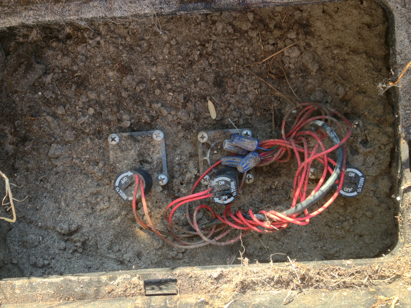
3. Now that you know which valve you want to remove, carefully dig the dirt away from the valve and expose the pipe on the downstream side of the zone valve. If you clear the dirt off the top of the zone valve it should have a flow direction arrow someplace on the valve body that points toward the outlet side. (It may be on the side of the valve, using a small mirror makes it easier to find it.)
Once you know which direction the water flows through the valve, cut out a short section of the pipe right after the valve. Water may squirt out when you make the first cut into the pipe, so be prepared to get some muddy water sprayed at you! A lot of water may drain out when you cut the pipe, depending on how much water was in the pipes and the slope of your yard. You may have to bail water out of the hole with a bucket to remove it. With the pipe section removed you can now use a wrench to unscrew the remaining pipe from the valve outlet. Take the pipe section you removed from the valve (with the threads on it) to a hardware store and buy a threaded plug of the same size and a roll of Teflon tape. Wrap several layers of the Teflon tape sealant onto the threads of the plug and then put the plug into the valve outlet opening. Hand tighten the plug, then use the wrench to tighten it another half turn. Do not overtighten it, if you overtighten the plug the valve body may split open. Now that valve zone is plugged off. You can remove the wires for that valve from the controller if you wish. Now remove any of the pipe or sprinklers you want from that valve zone.
You can remove the entire valve if you want to. I didn’t have you remove the valve because that does not require you to turn off the water to the entire sprinkler system, which is easier for most homeowners to do themselves.
To remove the entire valve: Turn off the water to the entire sprinkler system. Then manually turn ON the valve you want to remove, the sprinklers will come on for a few seconds then slowly shut off as the water discharges from the pipes and the pressure is released. If the sprinklers keep running the water is not shut off! Now follow the directions above. Once the outlet pipe section is cut and removed, cut the wires off the valve, then unscrew and remove the entire valve. Seal the ends of the wires with PVC glue or silicon caulk/sealer if you think you may ever want to use them again. Put a threaded cap on the pipe that formerly connected to the valve.
Removing sprinklers. To remove a sprinkler you can sometimes just grab the top of it and turn it counter-clockwise. It will unscrew from the pipe below it and then you can lift it out of the ground. Often you will need to dig away grass from it so you can twist it out. In most cases you don’t need to dig a big hole around the sprinkler head, just dig away enough dirt and grass to allow you to grip the sprinkler. Fill in the hole with dirt after you remove it. Assuming you are abandoning the pipes, there is no need to cap the pipe off below the sprinkler, just leave it there. If you don’t plan to ever use it, it doesn’t matter if it gets dirt in it.
Removing Pipes. Most of the time we just leave the pipes in the ground. They are a lot of work to remove and most of the time they don’t bother anyone if left buried. If the pipes are not very deep you can often pull them up using “brute force”. Dig down to expose the end of the pipe, grab the end and pull it up out of the ground. If there is thick lawn you may need to cut a slit in the lawn surface to allow the pipe to be pulled up easier. Use a edger to cut the turf directly above the pipe. A string trimmer with heavy string in it may be able to cut the turf. It may use up a lot of string!
I don’t recommend using a vehicle to pull the pipe out, but I know some will try it. If you do this and get yourself injured or killed, you will be featured in those “knuckleheads in the news” columns! If you try attaching a rope to the pipe and the other end to a garden tractor or truck to pull the pipe out of the ground – be very careful. Wear protective clothing, gloves, eye protection and a hard hat. Keep everyone else far away. Have someone there watching from a distance who can call 911 if you get hurt! Here’s why I say you shouldn’t do this: Plastic pipe breaks suddenly and violently when pulled hard. If the pipe or rope breaks while pulling on the pipe both the rope and the pipe can whip around violently and cause injury or damage, ie; break a window. The white hard PVC plastic pipe can shatter and release small, very sharp pieces of plastic that act like shrapnel and cut like dozens of little knives. If the pipe does not come out easily and you see the rope stretching, STOP, it’s going to break! Don’t be an idiot, use common sense and extreme care.
If you can’t pull the pipe up and you absolutely can’t just abandon it in place, the only way I know of to get it out is to dig it out. Ugghh. Lots of work.
Clogged Drainage or Irrigation Pipes
Q. I have a drainage pipe for my landscape that is clogged. I tried running a “snake” through it to clean it out, but it wasn’t able to do the job. Any suggestions?
A. I had a similar problem recently, it was with a sewer rather than a drain pipe, but the solutions are similar. My sewers backed up, after trying my short snake and getting nowhere with it I realized it was a major blockage and called a sewer cleaning company.Over the years I have come across a lot of clogged pipes in landscapes. They tend to fall into to categories when it comes to cleaning them out.
Dirt or Debris in the Pipe
When my sewer line backed up I called a sewer cleaning company and they came out and tried to snake it using a metal power snake. A snake is typically the first thing they try, it’s cheaper due to the low cost of the equipment they use, but it doesn’t really do a very good job as I discovered. In my case the standard metal snake would not budge the clog and the snake wound up all twisted up and jammed in the pipe. It took the poor guy a long time to get it out! So they moved up to using a hydraulic cleaning tool (aka hydro-jet, hydraulic flusher, hydro-scrub, etc.) This tool uses extreme high pressure water from a pump that is blasted through several tiny nozzles on the end of a PEX tube. The hydraulic cleaner blasted right though the blockage, plus it really cleaned out the pipe. It costs more than snaking, but it works great. My sewer has a clean-out opening near the street which allowed my to get a look into the pipe before and after the cleaning. After snaking the line using the metal snake there was still a lot of stuff that had built up stuck to the inside of the pipe. After the hydraulic cleaning it was almost completely clean inside. Pretty amazing, I was so impressed I decided to have the guy clean all my sewer pipes with it as a preventive measure. I would never go back to using a snake, next time I’ll just have them start with the hydraulic cleaner. The high pressure water just cuts through stuff. So if your blockage is caused by dirt and debris that has collected in the pipe, you can start with snaking it (you can rent a snake if you want to try it yourself.) If you have someone clean it for you I would just skip snaking it and have it hydraulic cleaned. Hiring a pro to snaking a pipe is generally about $50-100 USD, the hydraulic cleaning runs $150-200 USD. Costs are year 2013 for the Southern California area.
Tree Roots and Crushed Pipes
Sadly, my experience is that often a pipe that does not drain is not a blockage that can be removed with either a snake or a hydraulic cleaner. It is caused by tree roots actually crushing the pipe. If you have big trees in the vicinity of the pipe, this is likely the cause.
What happens is a trees roots create a “Y” where one root goes over the pipe while another passes under it. As the tree roots grow and increase in diameter they squeeze the pipe, they can exert an amazing amount of force! (You’ve probably seen places where tree roots have lifted concrete curbs and sidewalks, so you have seen for yourself how much force a root can exert.) If it is a plastic pipe they will squeeze it until it is flattened and no water can get through. I have seen this many times with PVC irrigation pipes and even with ABS sewer pipes. The corrugated poly drainage pipe often used for landscape drainage pipes, roof drains and sump pumps is very easily crushed. Unfortunately a drain cleaning tool like a snake or hydraulic cleaner can’t fix a crushed pipe. If you know where the pipe runs through the landscape you can use a “fish tape” to find out where the blockage is. if the pipe has an open end you feed the tape in there. If not, yuo may need to cut a section of the pipe out to insert the tape. Just feed the tape into the pipe until it hits the blockage. Now mark the location on the tape where it hit the blockage. Pull the tape out of the pipe and lay it along the known pipe route on top of the ground, with the location you marked at the point you inserted the fish into the pipe. The end of the tape should be in about the same location as the blockage. Dig up the pipe and you will very likely find a bunch of roots and a flattened pipe. Cut out the roots and the bad pipe and replace it. If the roots are large you may need to relocate the pipe so that it goes around them. Do not cut large roots that are close to the trees trunk without consulting an arborist. If you can’t afford an arborist or other landscape expert at least giving it a lot of thought before cutting the roots. Are there sufficient other roots to hold the tree? You can severely weaken the tree and cause it to topple in a wind storm. You might want to consider if it would be advisable to stabilize the tree with cables and stakes if you do cut the roots.
Double Check Backflow Preventer Problems
Throughout my tutorials and articles on irrigation system design I recommend against the use of double check type backflow preventers on irrigation systems connected to potable water supplies (drinking water). This article is an explanation of why.
A double check backflow preventer is simply two spring-loaded check valves in a row, with a shut-off valve on either end and test cocks to allow the unit to be tested for proper operation. The double check backflow preventer is the only true backflow preventer which does not have a vent to allow air to enter the lines or to allow water to escape when backflow occurs. It relies entirely on the tight seal of the two check valves to prevent backflow. While it may come as a surprise, the experts who regulate backflow preventers consider the lack of a vent to be a major problem, and thus they consider double check backflow preventers as appropriate only for low-hazard situations. More on this below.
So why can’t a double check backflow preventer be used with water containing hazardous substances? The answer is really pretty simple. Two check valves sounds like good protection, after all if one fails there is a backup, right? The problem is found in the cause of the check valve failure. They almost always fail because something gets stuck in them (sand, twigs, insects, clams) which prevents them from closing. Unfortunately, where there is one of those contaminants, there are often many! Thus while the chances of one check valve failing may be fairly low, the chance that the other check valve will fail at exactly the same time is very high. That is the reason why double checks can’t be used when hazardous substances may be present in the water.
Irrigation water is considered by many experts to be hazardous, this is especially true of the agencies that regulate health and safety laws. The reasoning is that dangerous chemicals (fertilizers, pesticides) as well as soil borne contaminates (animal excretions, decomposition) are found in irrigated areas and these substances may be drawn back into the irrigation water through the sprinklers or drip emitters when backflow occurs. This is especially likely if water ponds on the ground around a sprinkler head or emitter.
Pro Double Check Backflow Preventer Argument:
The double check backflow preventer is less susceptible to freezing damage because in most cases it can be installed below ground or inside a basement. This makes winterization of the irrigation system much easier. Supporters of double check backflow preventers also argue that irrigation water is not a hazard to health, it is merely objectionable (tastes bad, looks bad, or smells bad, but won’t make you sick). This point is essential, because pretty much all authorities agree that double check backflow preventers are not appropriate for use when health hazard substances are present in the water. The final argument often used in favor of double check backflow preventers is their lower cost to purchase.
Anti Double Check Backflow Preventer Argument:
The con argument is really simple, they claim that irrigation water is hazardous to your health, and thus a double check backflow preventer is not suitable. The argument goes something like this– whenever an irrigation cycle is completed, gravity causes at least some of the water in the pipes to run out onto the ground through the lowest sprinkler head or drip emitter (even if they are only an inch lower). When the water runs out a vacuum is created in the pipe. This vacuum sucks stuff from the ground into the pipe through the higher sprinkler heads or emitters. That includes stagnant water, dirt, fertilizer, bacteria, animal waste, and anything else present at ground level. All of those can be hazardous to your health. Once in the pipe they can then flow back into the water supply. So irrigation water is a health hazard.
What the organizations involved in the backflow industry say about double checks:
The AWWA (American Water Works Association) is an organization consisting of people interested in issues related to water. Most members are people who work for public or private water companies or who work for companies that make water related products (like the backflow preventer manufacturers). The AWWA publishes consensus standards which are created by committees made up of various Association members who debate and attempt to reach a consensus on what should be in the standard. To put it another way, these standards are based on the collective opinions of the committee members rather than on research or other factual data. This is not bad, but it is important to recognize that these standards are the result of a political, rather than scientific, process. The position of the AWWA on double checks is stated in standard “C510-92 Double Check Valve Backflow Prevention Assembly”. This standard says that double checks may be used for sprinkler irrigation systems, provided no chemicals are injected into the sprinkler water.
The Foundation for Cross-Connection Control and Hydraulic Research at the University of Southern California creates a set of standards which it publishes as the “Manual of Cross-Connection Control”. The Foundation also tests various makes and models of backflow preventers for compliance with the USC standards and gives approvals to those that meet the standards. The foundation is an independent organization that bases it’s decisions and standards on research data. The backflow preventers that pass the Foundation’s minimum standards and tests are listed in the official “List of Approved Backflow Prevention Assemblies”. USC rates undesirable water into 3 classifications; Pollutants (non-health hazard), Contaminants (minor health hazard), and Lethal Hazard (sewage or radiation present). The position of the Foundation on double checks is that “The DC may be used to protect against a pollutant only”. So is irrigation water a pollutant or contaminant? Back to that same old question…
My recommendation:
I do not recommend the use of double check backflow preventers on irrigation systems. I do not use double check backflow preventers on my projects except in very rare cases where I am either required to, or special conditions exist such as sprinklers mounted very high above the ground where contaminates can’t reach them. There is a very simple reason for this. I am a registered Landscape Architect, and as such I am required above all else to “protect the health, safety, and welfare of the public”. Thus I am held to a higher standard than a homeowner or other non-licensed person and my advise must reflect that. So if you write and ask me if I would recommend using a double check, even if you think you have a special circumstance that eliminates almost ALL of the risk, I am still likely to tell you no. Because that is what I have to tell you!
Your decision?
So, should YOU use a double check backflow preventer? Well, that is, of course, up to you. If you have a local regulating agency who says you MUST use a double check backflow preventer then you don’t have much choice. The good news is that I haven’t heard of any cases of anyone killed or disabled as a result of backflow from an irrigation system, as long as the irrigation system had some type of backflow preventer on it.
A final note:
I’ve taken a lot of heat from people over my position on Double Check Backflow Preventers. I’m rather tired of being flamed for it, it’s my opinion and that’s all. If you have a correction or addition to the arguments above I would love to hear it, and in most cases I will incorporate it into the arguments. If you simply disagree with my recommendation, that is fine, I don’t mind at all, but I don’t want to hear about it. I’ve tried to give my readers as fair as possible a view of both sides of the issue so that they can make a decision. I hope that I have accomplished that.
Pipe and Tube Pressure Loss Tables
Here are some pressure loss tables you can use to calculate the friction loss in your house or irrigation system mainline. This is the old-school, low-tech method. There are also free spreadsheets available (they use the free Open-Office spreadsheet program) on this website that will calculate pressure loss for you. The spreadsheets cover more types and sizes of pipe than these tables. I suggest using the spreadsheets, but these tables are handy if you want to do a quick look-up of a value, or just don’t do spreadsheets.
Quick background for those who linked to this page from a search for water pressure or something similar. As water flows through a pipe it losses pressure. The pressure is lost due to friction of the water against the pipe walls and also turbulence as the water tumbles around. Knowing how much pressure loss to expect is important. If there isn’t enough pressure left at the end of the pipe, then things like sprinklers, washing machines, dishwashers, faucets, toilets, etc. will not work. For very general purposes, most of the fore-mentioned items need at least 20 PSI of pressure to operate. Most will work much better at 30 PSI.
How To Use a Pipe Pressure Loss Table:
(PSI = pounds per square inch = lbs./sq.in.)
- Select the proper table for the type of pipe, i.e.; SCH 40 PVC, SCH 40 steel, polyethylene, copper, etc.
- Locate the proper column on the table for the pipe size.
- Read down the column to the row for the flow rate (GPM) in the pipe section. You will find a PSI loss value (given as PSI/100).
- Multiply the PSI loss value shown by the total length of the pipe section, then divide the product by 100. (PSI loss on these tables is given in PSI per 100 feet of pipe.)
- Pressure loss values highlighted in yellow italics are over 5 feet per second. This is a high velocity, but considered acceptable for short distances (less than 50 feet of pipe length.)
- Pressure losses greater than those shown on the chart can cause permanent and expensive damage to your plumbing. You must use a lower flow (GPM) in the pipe.
PSI Loss Value x Length of Pipe / 100 = PSI loss in pipe
Example: 1″ size, type SCH 40 PVC mainline. The length of the mainline pipe is 23 feet. The water flow rate through the mainline is 18 GPM. Using a pipe pressure loss table we find that the PSI loss for 1″ SCH 40 PVC at a flow rate of 18 GPM is 8.12 PSI per 100′. Therefore: 8.12 x 23 / 100 = 1.87 PSI – to simplify, you can round up the value to 2 PSI loss
(Note: PSI loss charts vary somewhat from each other. Other charts may result in an answer slightly different from the one in this example.)
PRESSURE LOSS TABLE FOR SCH 40 PVC PIPE
| FLOW GPM | 3/4″ | 1″ | 1 1/4″ | 1 1/2″ | 2″ | 2 1/2″ | 3″ |
|---|---|---|---|---|---|---|---|
| 1 | 0.13 | 0.04 | 0.01 | —— | —— | —— | —— |
| 2 | 0.45 | 0.14 | 0.04 | —— | —— | —— | —— |
| 3 | 0.95 | 0.30 | 0.08 | —— | —— | —— | —— |
| 4 | 1.62 | 0.50 | 0.14 | 0.07 | —— | —— | —— |
| 5 | 2.45 | 0.76 | 0.20 | 0.10 | —— | —— | —— |
| 6 | 3.44 | 1.06 | 0.28 | 0.13 | —— | —— | —— |
| 7 | 4.57 | 1.42 | 0.38 | 0.18 | —— | —— | —— |
| 8 | 5.85 | 1.81 | 0.48 | 0.23 | —— | —— | —— |
| 9 | 7.28 | 2.25 | 0.60 | 0.28 | 0.09 | —— | —— |
| 10 | 8.85 | 2.74 | 0.72 | 0.34 | 0.11 | —— | —— |
| 11 | 10.56 | 3.26 | 0.86 | 0.41 | 0.12 | —— | —— |
| 12 | —— | 3.84 | 1.01 | 0.48 | 0.14 | —— | —— |
| 13 | —— | 4.45 | 1.17 | 0.56 | 0.17 | —— | —— |
| 14 | —— | 5.10 | 1.35 | 0.64 | 0.19 | —— | —— |
| FLOW GPM | 3/4″ | 1″ | 1 1/4″ | 1 1/2″ | 2″ | 2 1/2″ | 3″ |
| 15 | —— | 5.80 | 1.53 | 0.72 | 0.22 | 0.09 | —— |
| 16 | —— | 6.53 | 1.72 | 0.82 | 0.25 | 0.11 | —— |
| 18 | —— | 8.12 | 2.14 | 1.01 | 0.30 | 0.13 | —— |
| 20 | —— | —— | 2.60 | 1.23 | 0.37 | 0.16 | —— |
| 22 | —— | —— | 3.10 | 1.47 | 0.44 | 0.19 | —— |
| 24 | —— | —— | 3.65 | 1.72 | 0.51 | 0.21 | 0.08 |
| 26 | —— | —— | 4.23 | 2.00 | 0.60 | 0.25 | 0.09 |
| 28 | —— | —— | 4.85 | 2.29 | 0.68 | 0.29 | 0.10 |
| 30 | —— | —— | 5.51 | 2.60 | 0.78 | 0.33 | 0.12 |
| 35 | —— | —— | —— | 3.46 | 1.03 | 0.44 | 0.15 |
| 40 | —— | —— | —— | 4.43 | 1.32 | 0.54 | 0.20 |
| 45 | —— | —— | —— | —— | 1.64 | 0.69 | 0.24 |
| 50 | —— | —— | —— | —— | 1.99 | 0.84 | 0.30 |
| 55 | —— | —— | —— | —— | 2.37 | 1.00 | 0.35 |
| 60 | —— | —— | —— | —— | 2.79 | 1.18 | 0.41 |
| FLOW GPM | 3/4″ | 1″ | 1 1/4″ | 1 1/2″ | 2″ | 2 1/2″ | 3″ |
| 65 | —— | —— | —— | —— | 3.23 | 1.36 | 0.48 |
| 70 | —— | —— | —— | —— | 3.71 | 1.56 | 0.55 |
| 75 | —— | —— | —— | —— | —— | 1.78 | 0.62 |
| 80 | —— | —— | —— | —— | —— | 2.00 | 0.70 |
| 85 | —— | —— | —— | —— | —— | 2.24 | 0.78 |
| 90 | —— | —— | —— | —— | —— | 2.49 | 0.87 |
| 95 | —— | —— | —— | —— | —— | 2.75 | 0.96 |
| 100 | —— | —— | —— | —— | —— | 3.02 | 1.05 |
| 110 | —— | —— | —— | —— | —— | —— | 1.26 |
| 120 | —— | —— | —— | —— | —— | —— | 1.47 |
| 130 | —— | —— | —— | —— | —— | —— | 1.71 |
| 140 | —— | —— | —— | —— | —— | —— | 1.96 |
| 150 | —— | —— | —— | —— | —— | —— | 2.23 |
| 160 | —— | —— | —— | —— | —— | —— | 2.51 |
| FLOW GPM | 3/4″ | 1″ | 1 1/4″ | 1 1/2″ | 2″ | 2 1/2″ | 3″ |
Pressure losses highlighted in yellow italics reflect flow velocity between 5 and 7 feet/second. Use care utilizing flow velocities in this range. Water hammer damage can result from a combination of high pressure and high velocity. Pressure losses shown are in PSI per 100 feet of pipe length.
PRESSURE LOSS TABLE, POLYETHYLENE PIPE
For SDR-7, SDR-9, SDR 11.5, and SDR 15 (all have the same inside diameter)
| Flow in GPM | 3/4″ | 1″ | 1 1/4″ | 1 1/2″ | 2″ |
|---|---|---|---|---|---|
| 1 GPM | 0.12 | 0.04 | 0.01 | 0.00 | 0.00 |
| 2 GPM | 0.45 | 0.14 | 0.04 | 0.02 | 0.01 |
| 3 GPM | 0.95 | 0.29 | 0.08 | 0.04 | 0.01 |
| 4 GPM | 1.62 | 0.50 | 0.13 | 0.06 | 0.02 |
| 5 GPM | 2.44 | 0.76 | 0.20 | 0.09 | 0.03 |
| 6 GPM | 3.43 | 1.06 | 0.28 | 0.13 | 0.04 |
| 7 GPM | 4.56 | 1.41 | 0.37 | 0.18 | 0.05 |
| 8 GPM | 5.84 | 1.80 | 0.47 | 0.22 | 0.07 |
| 9 GPM | 7.26 | 2.24 | 0.59 | 0.28 | 0.08 |
| 10 GPM | 8.82 | 2.73 | 0.72 | 0.34 | 0.10 |
| 3/4″ | 1″ | 1 1/4″ | 1 1/2″ | 2″ | |
| 11 GPM | 10.53 | 3.25 | 0.86 | 0.40 | 0.12 |
| 12 GPM | 12.37 | 3.82 | 1.01 | 0.48 | 0.14 |
| 13 GPM | 13.34 | 4.43 | 1.17 | 0.55 | 0.16 |
| 14 GPM | 16.45 | 5.08 | 1.34 | 0.63 | 0.19 |
| 15 GPM | 18.70 | 5.78 | 1.52 | 0.72 | 0.21 |
| 16 GPM | 21.07 | 6.51 | 1.71 | 0.81 | 0.24 |
| 17 GPM | 23.57 | 7.28 | 1.92 | 0.91 | 0.27 |
| 18 GPM | 26.21 | 8.10 | 2.13 | 1.01 | 0.30 |
| 19 GPM | 28.97 | 8.95 | 2.36 | 1.11 | 0.33 |
| 20 GPM | 31.85 | 9.84 | 2.59 | 1.22 | 0.36 |
| 3/4″ | 1″ | 1 1/4″ | 1 1/2″ | 2″ | |
| 22 GPM | 38.00 | 11.74 | 3.09 | 1.46 | 0.43 |
| 24 GPM | 44.65 | 13.79 | 3.63 | 1.72 | 0.51 |
| 26 GPM | 51.78 | 16.00 | 4.21 | 1.99 | 0.59 |
| 28 GPM | 59.40 | 18.35 | 4.83 | 2.28 | 0.68 |
| 30 GPM | 67.50 | 20.85 | 5.49 | 2.59 | 0.77 |
| 32 GPM | 76.06 | 23.5 | 6.19 | 2.92 | 0.87 |
| 34 GPM | 26.29 | 6.92 | 3.27 | 0.97 | |
| 36 GPM | 29.22 | 7.69 | 3.63 | 1.08 | |
| 38 GPM | 32.30 | 8.50 | 4.02 | 1.19 | |
| 40 GPM | 35.52 | 9.35 | 4.42 | 1.31 | |
| 3/4″ | 1″ | 1 1/4″ | 1 1/2″ | 2″ | |
| 42 GPM | 38.88 | 10.24 | 4.83 | 1.43 | |
| 44 GPM | 42.43 | 11.16 | 5.27 | 1.56 | |
| 46 GPM | 46.01 | 12.12 | 5.72 | 1.70 | |
| 48 GPM | 49.79 | 13.11 | 6.19 | 1.84 | |
| 50 GPM | 53.70 | 14.14 | 6.68 | 1.98 | |
| 55 GPM | 16.87 | 7.97 | 2.36 | ||
| 60 GPM | 19.82 | 9.36 | 2.77 | ||
| 65 GPM | 22.98 | 10.86 | 3.22 | ||
| 70 GPM | 26.36 | 12.45 | 3.69 | ||
| 75 GPM | 29.96 | 14.15 | 4.19 |
Pressure losses highlighted in yellow italics reflect flow velocity between 5 and 7 feet/second. Use care utilizing flow velocities in this range. Water hammer damage can result from a combination of high pressure and high velocity. Pressure losses shown are in PSI per 100 feet of pipe length.
Pressure Loss Table, Type K Copper Pipe or Tubing
Type K copper pipe has the thickest wall and highest pressure ratings of the common copper tubing types. In order of wall thickness, common copper tubing types are Type M (thinnest), Type L, and Type K (thickest). Type L is commonly used for household plumbing. Type K is most often used to make short threaded-end nipples. If you don’t know what Type the pipe is, assume it is Type K.
| Flow in GPM | 1/2″ | 3/4″ | 1″ | 1 1/4″ |
|---|---|---|---|---|
| 1 GPM | 1.20 | 0.23 | 0.05 | 0.02 |
| 2 GPM | 4.33 | 0.77 | 0.18 | 0.06 |
| 3 GPM | 9.17 | 1.65 | 0.38 | 0.13 |
| 4 GPM | 15.67 | 2.78 | 0.68 | 0.22 |
| 5 GPM | 4.21 | 1.02 | 0.33 | |
| 6 GPM | 5.90 | 1.44 | 0.46 | |
| 7 GPM | 7.84 | 1.90 | 0.61 | |
| 8 GPM | 10.03 | 2.46 | 0.78 | |
| 9 GPM | 12.48 | 3.03 | 0.97 | |
| 10 GPM | 15.15 | 3.68 | 1.18 | |
| 11 GPM | 4.40 | 1.41 | ||
| 12 GPM | 5.17 | 1.66 | ||
| 13 GPM | 6.00 | 1.93 | ||
| 14 GPM | 6.88 | 2.21 | ||
| 15 GPM | 7.81 | 2.51 | ||
| 16 GPM | 8.42 | 2.83 | ||
| 17 GPM | 9.42 | 3.16 | ||
| 18 GPM | 3.52 | |||
| 19 GPM | 3.89 | |||
| 20 GPM | 4.28 | |||
| 22 GPM | 5.10 | |||
| 24 GPM | 5.99 | |||
| 26 GPM | 6.95 |
Pressure losses highlighted in yellow italics reflect flow velocity between 5 and 7 feet/second. Use care utilizing flow velocities in this range. Water hammer damage can result from a combination of high pressure and high velocity. Pressure losses shown are in PSI per 100 feet of pipe length.
PRESSURE LOSS TABLE, TYPE L COPPER PIPE OR TUBING
Type L copper tube is the type most commonly used for household plumbing. In order of wall thickness, common copper tubing types are Type M (thinnest), Type L, and Type K (thickest). If you don’t know what Type the pipe is, assume it is Type K.
| Flow in GPM | 1/2″ | 3/4″ | 1″ | 1 1/4″ |
|---|---|---|---|---|
| 1 GPM | 0.95 | 0.16 | 0.04 | 0.02 |
| 2 GPM | 3.44 | 0.57 | 0.15 | 0.06 |
| 3 GPM | 7.29 | 1.20 | 0.33 | 0.12 |
| 4 GPM | 12.41 | 2.05 | 0.56 | 0.20 |
| 5 GPM | 18.77 | 3.09 | 0.85 | 0.30 |
| 6 GPM | 4.34 | 1.18 | 0.43 | |
| 7 GPM | 5.77 | 1.58 | 0.57 | |
| 8 GPM | 7.39 | 2.02 | 0.72 | |
| 9 GPM | 9.19 | 2.51 | 0.90 | |
| 10 GPM | 11.17 | 3.05 | 1.10 | |
| 11 GPM | 3.64 | 1.31 | ||
| 12 GPM | 4.28 | 1.54 | ||
| 13 GPM | 4.96 | 1.78 | ||
| 14 GPM | 5.69 | 2.04 | ||
| 15 GPM | 6.46 | 2.32 | ||
| 16 GPM | 7.28 | 2.62 | ||
| 17 GPM | 8.15 | 2.93 | ||
| 18 GPM | 9.06 | 3.25 | ||
| 19 GPM | 3.60 | |||
| 20 GPM | 3.96 | |||
| 22 GPM | 4.72 | |||
| 24 GPM | 5.55 | |||
| 26 GPM | 6.43 |
Pressure losses highlighted in yellow italics reflect flow velocity between 5 and 7 feet/second. Use care utilizing flow velocities in this range. Water hammer damage can result from a combination of high pressure and high velocity. Pressure losses shown are in PSI per 100 feet of pipe length.
Rainbird Anti-Siphon Valve Leaks, Won’t Fully Close
Rainbird’s residential series valves have a small internal filter which can become clogged with grit, even with reasonably clean water supplies. When this filter becomes clogged the valve will no longer fully close when operated automatically. Here’s how to clean the filters.
Continue reading Rainbird Anti-Siphon Valve Leaks, Won’t Fully Close
How to Remove PVC Cement From Your Hands
There are several hand cleaner products made for removing PVC cement/glue from your hands. Most combine a solvent with an abrasive grit and a hand moistening lotion into a single product. The ones I have used work very well. They are typically sold at irrigation supply stores. For some reason I have never seen them sold at the home improvement stores where homeowners tend to buy irrigation supplies.
For the “weekend warrior” who just needs to get the cement/glue off infrequently, acetone will remove it quickly. Be sure to immediately wash any skin you apply acetone to thoroughly with soap and water after getting the glue off. Do not leave acetone on your skin!
![]() Repeated skin exposure to acetone may cause serious health issues, so it should not be used by pros who need to remove glue from their hands often. Be sure to read and follow all precautions on the acetone can.
Repeated skin exposure to acetone may cause serious health issues, so it should not be used by pros who need to remove glue from their hands often. Be sure to read and follow all precautions on the acetone can.
How to Remove Paint from PVC Pipe
PVC pipe that is exposed to sunlight should be painted to prevent sunlight from destroying the plastic. But what if you need to repair the PVC pipe later? You can’t glue pipe that has paint on it. In fact, you need to remove all of that paint from the area to be glued, even a small amount may cause leaks in the glued joint.
Using a small brush “paint” acetone onto the area of pipe where you want to remove the paint. (PVC primer will also work as a replacement for acetone, but the purple color makes it hard to make sure all the paint is off.) Allow the acetone to soak in for a few seconds then scrape off the paint with a knife blade or other metal edged tool like a putty knife. If some of the paint doesn’t easily come off re-coat the paint with more acetone. Once most of the paint is off, apply another coat of acetone. This time use a paper towel to wipe off the remaining paint. You may need to wipe down the PVC pipe 2-3 times with fresh paper towels to get a nice clean white surface. Now you can glue your joint using the normal method for gluing PVC pipe as described on the cement/glue can. The acetone will leave the pipe surface feeling sticky, that’s OK, you don’t need to wait for it to dry before you glue the joint. The primary ingredient in the purple PVC primer that is used to clean and prepare PVC pipe for gluing is acetone.
![]() Use caution when working with acetone. Read and follow the warnings on the can. Repeated skin exposure to acetone may be harmful to your health.
Use caution when working with acetone. Read and follow the warnings on the can. Repeated skin exposure to acetone may be harmful to your health.
Should the Pipe be the Same Size as the Sprinkler Inlet?
Q. I was wondering if the size of the water pipe makes a difference in the performance of the sprinkler head — 3/4 inch or 1 inch ?? I have the option of supplying my sprinklers with either a 3/4 inch or a 1 inch water supply line.
A. Yes, the pipe size does make a difference. The industry “rule of thumb” is that the pipe should never be smaller than the sprinkler inlet, although there is no technical reason for that. There could be situations where a smaller pipe will work just fine. But they are not common. The truth is that in most cases the appropriate pipe size is one to two pipe sizes larger than the inlet. I’ve seen some sprinkler systems where the pipe needed to be several times larger than the sprinkler inlet, although those situation are very rare. To confuse things more, some sprinklers have two different size inlets. In the case of two inlet sizes I would typically use a pipe the same size or LARGER than the largest inlet.
The Right Way:
Sprinklers require water pressure to operate. Every sprinkler has an optimum water pressure that makes it work best. Water pressure is lost as the water moves through pipes, valves, fittings etc. This is called “friction loss” in the irrigation industry (although the pressure loss comes from more than just friction.) So the size of pipe you use to supply the sprinkler head with water must not only supply the right amount of water, it must also not reduce the pressure below the amount needed to operate the sprinkler efficiently.
Unfortunately there is not a standard “use this size pipe with this size/brand/model sprinkler head” solution. The right pipe size may vary with every irrigation system. Figuring out what size to use is not an easy task. My free tutorial on Sprinkler System Design takes you through the process step-by-step. While it seems simple enough to stick a sprinkler on the end of a pipe, in truth, irrigation systems require a considerable amount of careful design calculations to work correctly and efficiently. (That “efficient” part is really important, a sprinkler system designed wrong can easily use 2-3 times more water than one designed right.) The first couple of pages of the tutorial give a more detailed explanation of what is involved in irrigation design and answer a lot of the “why?” questions that people have at this stage. Then the tutorial will take you step-by-step through how to figure out what size pipe it should be. If you are installing a new irrigation system, then the tutorial is the way to go. Unfortunately once you have the system installed is not the best time to discover you should have had a better design up front! I’m always telling people that delaying the process for 2-3 weeks to struggle through doing a good design may seem like too much work. But when you have it installed and you realize you wasted hundreds, maybe thousands of dollars on a system that doesn’t work… wow! I get lots of email from people who are not happy when they realize that it often costs more to fix a poorly designed sprinkler system than they paid for it!!! Please don’t be another one of them. Better to spend another few weeks watering by hand and take the time to create a good design.
Method for Calculating the Size for a Pipe:
If you want to skip straight to the step of determining a sprinkler system pipe size, you can look at How to Calculate a Lateral Pipe Size. This page has a spreadsheet and instructions you can use that will figure out the pressure loss in a length of pipe. You are jumping to the end of a tutorial when you do this, so you may need to go back a few pages in the tutorial to get the background information you need. You are going to need to know the type of pipe you are using so you can get the right spreadsheet. You will also need to find out the GPM of your sprinkler head (see the manufacturer’s website for this) and how much pressure loss (“PSI Loss” column on the spreadsheet) is allowable in your pipe. Finding this PSI Loss value is going to be the hard part since you are jumping to the end of process. You will probably need to make an educated guess (assuming you don’t want to just go back to the beginning of the tutorial and do it the right way.) If you need to guess at the PSI Loss value, I would suggest a maximum value of 0.5 PSI Loss. That’s 1/2 of a PSI in each pipe section. Remember that is an educated guess and there is no way I guarantee it will work! You are taking a risk to shortcut the process.
Risky but Expensive Simple Solution that Usually Works:
If you really don’t want to deal with looking stuff up and doing calculations, one solid rule in irrigation design is that a pipe can never be “too large”. (For a detailed discussion of why, see why a smaller pipe will not increase pressure.) So if you are in doubt, you always use a larger pipe size. You could hook up a 1/2″ sprinkler to a 10″ pipe and the sprinkler would work just fine. The 10″ pipe would not be kind to your budget, however.
You can use this “larger is never worse” rule to your advantage. If you really don’t want to deal with calculating the right size, one way to solve the problem is to use a ridiculously over-size pipe. Ie; if the sprinkler has a 1″ inlet use a 1.5″ pipe and you will probably be safe. Of course this may well be overkill as well, but if you don’t want to do all the calculations, then you pay the price of a larger pipe and go with over-kill. Remember you do this solely at your own risk!
Watering a very narrow 30″ wide lawn strip
Q. I need to water a 2.5′ wide by 21′ long grass strip in the middle of my driveway. What is a good method for this narrow an area? My home is located in Southern California.
A. Irrigating lawn in areas less than 4′ wide is very hard and results in a lot of wasted water. It is illegal to install a grass area less than 4 to 6 feet wide in many cities, especially in California and other western States, including ALL of Arizona and most of Nevada (the minimum width varies from town to town.) Enforcement is typically limited to new development, but if you get a permit from the city for the work you may get nailed on this issue.
Using Sprinklers
If you do use sprinklers there is going to be a lot of water waste from over-spray onto the concrete. It will likely run down your driveway and when (not if) the next big drought cycle hits and they start with the “water police” thing you will likely have to stop watering your strip or risk a “fix it” ticket.
If you do use sprinklers you will reduce the radius of each sprinkler to your 30″ width and then you reduce the distance between sprinklers by a similar %. I recommend using side-strip sprays rather than the center-strip type as you will have a lot less over-spray on to the concrete with them. The side strip side are installed down both sides of the strip. Center spray types are installed down the center of the strip. Using center strips type will require half as many sprinklers, but the cost of this initial savings is lousy performance, poor efficiency, and lots of wasted water (it is common when using center strips that 50% or more of the water applied will be wasted.) So let’s say you decide to use 4′ x 12′ pattern side-strip spray nozzles in 4″ pop-up bodies. Since your area is only 30″ wide you would need to reduce the spray width from 48″ to 30″. That would be 62% of 48″ ( 30″ / 48″ = 0.625). So you would also need to reduce the 12′ distance down to 62% also, which is 7.5′ (12′ x 0.62 = 7.44′). So in your 30″ x 21′ area you would space the heads 7′ apart on both sides. After installing the system you would reduce the radius of each head as best you can using the radius reduction screw. It is unlikely you will be able to avoid some over-spray onto the walk as noted earlier. If you decide to use center strip nozzles the procedure and spacing would be the same, there would only be one row of heads, however, installed right down the center of the strip. With center strips you will have to allow more water to overspray onto the cement driveway, if you don’t you will get dry yellow edges. If you want a better explanation of why see this page on sprinkler spacing.
Using Subsurface Drip
Your other option is to use subsurface drip. This is what I would do. In this case I would use three drip tubes running the length of the grass strip. Place one down the middle and the other two should be 4″ in from the edge of the driveway concrete on each side. Use dripperline with 1 gph emitters spaced 12″ apart. Netafim, Rainbird, and Toro all make subsurface dripperline. Make sure the dripperline is a model that the manufacturer claims in their literature is for subsurface installation. Subsurface dripperline uses a different type of emitter designed to keep out dirt and roots. Read my drip guidelines for info on filters and pressure regulators you will need. The salesperson at the irrigation store may tell you that you only need two tubes, which normally would be correct, they typically are spaced 18″ apart, not 12″. There are a couple of reasons I am suggesting 3 tubes rather than 2. First is to get the total flow up because the area is so small and most automatic solenoid valves don’t work very good at really low flows. Another reason is that the concrete on both sides absorbs and radiates a lot of heat, and this is going to make your little lawn strip dry out fast. That’s also why I suggest the dripperlines at the edges of the area be 4″ from the concrete, otherwise the lawn edges right up against the concrete tend to dry up and turn yellow. You are going to need to be careful in selecting your valve, the dripperlines in your 21′ long area are so short that the total flow using 1gph emitters is only going to be 1 GPM; (3 tubes, 20′ long with 1gph emitters every foot. So 20′ x 3 tubes = 60′ of tube. 60′ of tube x 1gph/ft = 60 gph. 1 gpm = 60 gph.) A lot of automatic valves will not work at flows that low. Make sure the rated flow range in the literature for the valve goes that low.
To install your drip system remove the top 5″ of soil from your planter. Now till the soil another 4″ deep. Tamp down the soil to lightly compact it and get rid of air voids. A 8″x8″ hand tamper tool is good for this, you can buy one at any decent garden shop or home improvement store. Now place your dripperline tubes down on top of the soil and use steel erosion control staples to hold the tubes in place. Put a stake every 36″. You can buy the stakes at the irrigation store, they all carry them. The metal stakes work much better than the plastic ones made for drip tube. The stakes are very important, they will rust into the soil and hold the tubes in place. Without them the empty tubes will float to the surface during the winter when the soil becomes saturated during rain storms.
Now put down the final 3″ of soil over the top of the tubes, tamp it down and install your sod (which should be about 1″ thick and should bring the sod surface up even with the top of the concrete.) You will need to lightly hand water the sod for a week or two to keep it cool and moist. It needs time to grow roots down to where the subsurface water from the dripperline is. Slowly back off the hand watering after a couple of weeks. Watch the sod’s color to see how well it is rooting in. If the sod is still in need of top-watering by hand it will turn a dull “flat green” color. When you first install it, the sod will be that dull flat green color because it is stressed from the cutting,shipping and installation. It’s easier to see the color if you stand back and look at it from a distance. Right after you install the sod take a minute to look carefully at it and notice the stressed dull color. Then also note the brighter green color it changes to after you water it the first time it. Now you know what stressed sod looks like and what to look for over the next few weeks. If it is hot or the warm winds are blowing when you install the sod you may need to hand water it more often. Usually watering a couple of times a day is sufficient until the sod is established.
Creating Water-Proof Irrigation Wire Connections
Water-proofing your irrigation system’s wire splices is one of the most critical tasks in any installation or repair that involves wire splices. The splices need to be completely water-proof. Taping them up with electrical tape will NOT work for this! The electrical tape will allow water into the splice as it becomes old, brittle, and the adhesive on it dries out. If you don’t water-proof your splices it WILL cause your valve to fail! Don’t save a buck on a wire splice and ruin a $20 valve! I’ll explain in detail why waterproofing is so important later, first let’s get down to the details on how to make a good waterproof wire splice.
General Things That you Need to Know about all splices!
Caution: The methods described below are intended for low-voltage wires of 24VAC or less, such as those used in typical irrigation system controls. They should not be used for higher voltages.
DO NOT BURY SPLICES directly in the ground. Put a box around them to protect them and to help you find the later. A small plastic utility box works fine. Glue a large steel washer to the bottom of the box lid using epoxy. This will allow you to find the box with a metal detector if grass grows over it. Splices are the most likely place a wire will short out in the future, so a box makes the splices easier to find and repair.
2-wire irrigation systems: These are a newer type of system that uses only 2-wires to control all the valves. The irrigation controller sends a signal through the valves to a decoder at each valve. The decoder then allows power to the valve solenoid only when told to by the controller. These types of systems depend on electrical “signals” sent from the controller through the wire to the decoder. Any voltage leak at a splice can severely impact the signal and cause the system to malfunction. For this reason splices for 2-wire systems need to be made much more carefully. Many of the 2-wire manufacturers have specific splice methods they require be used in order to protect your warranty. Be sure to use these if required!
Not sure if your system is 2-wire? As i write this in 2013, 2-wire systems are seldom used on residential systems, but they are also gaining popularity and will probably start showing up soon, first on larger systems. The controller case normally will be clearly labeled as “2-wire”. A 2-wire system will also have a “decoder unit” installed on the wires at each valve. Standard irrigation control systems have two wires going to each valve. But in a standard system one of the wires goes to a single valve and only that valve. So if you have 4 valves there will be 5 wires (1 common shared by all the valves, + 1 individual wire to each of 4 valves = 5 wires.) On a 2-wire system with 54 valves there would be only 2 wires and each valve would have a decoder unit installed on it. The presence of a decoder to be installed at each valve is the best way to tell if it is 2-wire.
The best way to make the splice is to use special water-proof splice connectors that you can buy at any hardware store. These are made for sealing outdoor wire connections and work very well. There are many different styles and types available.
Water-Proof Twist On Connectors – “Nut” Style or “Wing” Style
Most of the connectors currently used by pros consist of an twist on type wire connector that is filled with a water sealing grease. Sometimes these are called water-proof “nut” or “wing type” connectors. These are inexpensive and very simple to use. Here are general instructions for use since a lot of these inexpensive connectors are sold without instructions. If instructions came with the connectors please use those instructions, as they are intended for the actual connectors you bought!
- For every 3 connections you need buy 5 connectors. Why? Because you will probably make several bad splices, and you will have to remove those connectors and toss them in the trash. They can’t be reused because when you remove them a lot of the sealer comes out with the wire. (If you look close most connectors actually say “do not reuse” or similar language on them.)
- Start by stripping the insulation off the end of the wires to expose the bare metal wire. Do not strip off too much insulation, the exposed bare wire should be about 1/2 the length of the connector body. You can splice 3 wires together easily using a single connector. It’s OK to put 4 or 5 wires in a connector, but be warned that it gets a lot more difficult getting the wires to stay in the connector when you use more than 3 wires.
- Place the bare ends in one hand and using your other hand, align the wires side-by-side, so the ends of the bare sections are lined up together. Those ends need to all go into the connector together at the same time, so hold the wires tight and don’t let them slip out of position. Do not try to insert an additional wire into a wire connector that already has wires spliced together in it. You need to remove all the wires and redo the splice to add more wires.
- Push the connector down over the bare ends of the wire. Twist the connector clockwise to screw it on. Hold the wires firmly in position as you twist the connector over them. The connector has threads, a spring, or barbs inside it that will grab the wires and cinch them together tightly as you twist it on. Stop twisting when you feel substantial resistance.
- Hold the connector in one hand and tug on each of the wires with the other to make sure the wires are secure and will not pull out. If a wire feels loose or pulls out, disassemble the entire splice and try again. Use a new connector as some of the sealer will probably be lost when you remove the connector, and it needs all the sealer for a good seal. If the wires still pull out after another try you are probably using the wrong size connector.
- Finally make a visual inspection of the splice. The insulation on the wire should be fully inserted into the sealer gel or grease. No bare wire should be visible. That’s all there is to using twist on wire connectors, they are very quick and easy.
The connector size is important when using twist on connectors! Be sure you buy and use the correct size connector for the wire sizes you are splicing. The package will list the various wire size combinations that the connector works on. The connector colors indicate the connector’s size and most are standardized. Here are some general guidelines. Warning: There are some brands that do not follow these color guidelines so double check the instructions on the package!
Connectors for #18 wire. Most residential irrigation systems use #18 size wire, this is the size of most of the multi-wire underground irrigation cables sold in hardware stores. Unfortunately the colors for these connectors are not standardized. Most I have seen are dark blue or black. Make sure it says it will connect 2- #18 wires.
Connectors for #14 & #12 wire. Larger irrigation systems and commercial irrigation often use individual #14 wires. Sometimes #12 will be used for irrigation systems with very long distances between the controller and the valve. Most often these connectors are yellow. Note: Most of the yellow connectors I have seen will NOT connect a single #14 wire to a typical valve solenoid wire. For this you will probably need the smaller #18 wire connectors above.

Mechanical Clip Style Non-Stripping Connectors
Clip style is a catch-all name I use for the various types of connectors that use a mechanical clamping system to grab and bite into the wire. Typically with this type of connector you push the wire into a round slot on the connector, and then squeeze some type of clamp that bites into the wire to hold it in place. Some require pliers to squeeze the clamp into the wires. The most popular of these types of connectors for irrigation use is the Blazing Snaploc BVS Series wire connectors and the 3M Scotchlok 314 series connectors. These connectors are more expensive but make a very secure connection almost always on the first attempt. You won’t need to buy nearly as many extras for bad splices.
Container Type Connectors
These connectors are a two piece, two step system. You connect the wires together using either a standard twist type wire connector, a crimp sleeve, or even soldering the wires together. Then you shove the splice into a container filled with a water-proofing grease or jell and snap a retainer lid closed to hold the splice inside the container.
A variation on this type of connector is the original waterproofing method used back when I started in the business. You mixed a 2-part epoxy resin in a small plastic envelope and then shoved the splice into the envelope so it was covered in resin. The resin was allowed to harden creating a solid water-proof seal. Unfortunately the resin was a carcinogen. I don’t think these are sold any longer.
Pump Cycles On Briefly When Irrigation is Off
Q. My irrigation pump runs fine when the system is operating, but after it turns off it cycles on for 5 seconds every 10 minutes or so.
A. If you are using a pressure switch and pressure tank to turn the pump on and off my first guess would be that you have a water leak in your irrigation system. The water leaks out, which cause the water pressure to drop, then the pump kicks on and recharges the pressure. Then the pump shuts off again. That would cause exactly this symptom.
Knowing the problem is the easy part. Finding the leak, that could be harder to do. It could be a zone valve that isn’t turning off all the way or it could be a leaky pipe. You can narrow the search area a little, the leak will be someplace in the pressurized part of the system, that is, between the pump and the zone control valves. Start by looking for obvious dripping, then look for someplace that seems wetter than it should. If it is a leaky zone valve then the water will be leaking through the valve into the sprinkler zone pipes and will dribble out at the lowest sprinkler head. So look at the sprinkler heads. There will be a small “swampy” area around the lowest sprinkler head that is controlled by that valve.
How to Fix a Automatic Irrigation Valve that Won’t Open
Check The Dumb Stuff.
If the valve won’t open at all, or doesn’t fully open, start with the obvious things just to be certain. I know, any idiot knows better, but even us pros periodically overlook something really simple and obvious.
Tip: There are labeled photos of some of the more popular valve models showing the various valve controls (such as flow-controls, on/off levers, and bleed screws) mentioned in this article at this page: Anti-Siphon Valves with Parts Labeled.
- Is the water supply turned on?
- Is there a shut off valve on the water supply that may have been closed? Once I had a system I couldn’t get to work, couldn’t find any closed valves, but still no water to the sprinklers. Turned out the city water company had closed a valve in the street for street work they were doing and forgot to reopen it!
- Check the flow control on the valve to make sure it isn’t closed or partially closed. It is often desirable for the flow control to be left partially closed, but if it is restricting the flow too much that could be the problem. On some valves the flow control doesn’t have a handle, it is just a small screw in the valve lid. If unsure, look up your valve model at the manufacturer’s website to see if they have a drawing of the valve showing a flow control device location. Unfortunately, some inexpensive valves do not have a flow control device.
Manual Operation Test
Try manually opening the valve, using the on/off lever on top of the valve body. Some valves use a bleed screw to manually open them, so if you don’t see a lever labeled on/off or open/close, look for a screw, typically the screw has a knob handle to allow it to be twisted by hand. Do not fully remove a bleed screw! Just turn it about 1-2 to 1 full turn, water will squirt out from under the screw and the valve should open. Some valves have both a bleed screw and a on/off lever, on those valves I generally use the bleed screw as I have found it works better if the valve is being stubborn. If the valve opens correctly and fully when using the manual open lever or bleed screw, then the problem may be electrical. If the valve does not open fully when using the manual open feature, skip over the next section on electrical problems.
Basic Electrical Tests
If you don’t have a valve actuator test unit, start by making yourself a home-made valve activator using three nine-volt batteries. See my page with full instructions for making a irrigation solenoid valve activator (it’s easy and only takes about 2 minutes!)
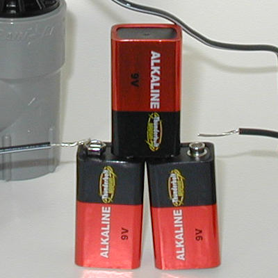
Now use your actuator to test your solenoid and wires:
- NOTE: make sure you are using fresh, brand new batteries in your actuator! It takes a lot of amperage to open a valve and worn or old batteries won’t do the job. Don’t waste your time tracking down false results caused by bad batteries!!!
- Note #2: 24 VAC does not feel good if you shock yourself with it, especially if you are wet. Don’t touch bare wires without rubber gloves on!
- Disconnect the wires from the valve solenoid. Touch the valve solenoid wires to the terminals on your activator. The valve should open. If the valve fully opens then the problem is NOT the valve, the problem is with the wires leading from the controller (timer) to the valve, or possibly the controller is broken. Continue with the next step. If the valve does not open, then skip the rest of the electrical diagnosis items. The problem is with the valve or the valve solenoid.
- Controller problems are very rare, it is much more likely the problem is a broken wire. Do NOT try to test the controller by using a wire to create a short-circuit “spark” between the terminals! You may fry your controller! First reread the controller manual on how to wire the valve circuits and make sure you don’t have them wired wrong. Optional: You can test the controller using a multimeter if you have one and know how to use it. The controller output to the valves is 24 VAC. Most modern controllers will show a positive test for 24VAC even if the circuit is off, you need to test the circuit with a load. Don’t panic if you don’t know what that means or don’t have a multimeter. Just go to the next step.
- You can test the wire very simply. If the wires from the controller to the valve are disconnected from the valve reattach them to the valve solenoid now.
- Next remove the wires for the common and the “lead” wire circuit to your valve from the controller terminals.
- Attach your valve actuator to the 2 wires at the controller end, just like you did to the solenoid wires. The valve should come on. If it doesn’t open, or only opens partially, the wires from the controller to the valve are either damaged (cut or short circuiting), or you are testing the wrong wires. Are you sure you have the correct pair of wires for this valve? That’s often the problem with a newly installed system! It’s pretty easy to get the wires mixed up, especially if they do not have color-coded insulation. Another source of the problem may be damaged insulation on the buried wire. If the insulation on the wire has been removed or damaged someplace along the length of the wire it can cause a voltage leak. A nick or partial cut in the wire may cause resistance to the current in the wire. These wire problems cause the solenoid to not receive sufficient power to fully open the valve.
- If the valve does turn on fully the problem is the controller. Most modern controllers are not user repairable. If it is under warranty contact the manufacturer for instructions. They may ask you to do some additional tests. If the controller is not still under warranty you can contact a professional irrigation repair outfit for a repair quote. For most low-cost homeowner controllers it is cheaper to just replace the controller with a new one. If your current controller is not a Smart Controller you should consider replacing it with one. A self-adjusting Smart Controller will save you a lot of water and effort.
Valve Cleaning and Repair
If you’ve tested the controller and wires and they are OK, then the problem is with the valve itself. You have two choices: remove and replace the valve, or disassemble the valve to look for problems. Which way you go depends on which is easier for you to do. I generally try to clean the valve rather than replace it at this point.
Replacing a valve: Removing and replacing a valve can be a big job if the valve is fully installed. Basically this is a swap out, take a photo of the old valve before you remove it, then remove it and install the new one in it’s place. You probably will need to cut the pipe on the outlet side of the valve so you can turn the valve body to unscrew it from the inlet pipe and get it out. Some valves are installed so close together that you need to cut the pipe on both the inlet and outlet sides, this is especially true of anti-siphon valves. Once the old valve is out, you install a new one in the same location. Finally you need to repair the pipe if you cut it. If the pipe is PVC they make special couplers for repairing pipes that make the job easier. Remember to completely water proof all the wire splices!
Note: a lot of anti-siphon valves are not properly installed. Even sprinkler installation companies don’t use the care they should to insure correct installation, and a incorrect installation may be the source of your valve problems. See the article on How to Properly Install an Anti-Siphon Valve to help you get it in right this time!
Clean & Repair a Valve: Most people try to repair the valve rather than replace it. I really think a repair is often easier at this stage. If you do proceed with disassembling the valve be sure to notice how all the parts fit together so you can reassemble it when done. Tip: take photos of the valve and how the parts fit together as you disassemble it!
- If the valve is more than a couple years old you might want to purchase a repair kit for the valve make and model (see bottom of this page for examples of what to look for.)
- Turn off the water supply to the valve. Remove the solenoid by unscrewing it. Note: each manufacturer’s valve is slightly different, but the basics are the same. Your valve may look different from the Water-Master brand valve shown in these photos.
Remove solenoid The bottom of the solenoid has a spring-loaded plunger in it. After removing the solenoid hold it in one hand and press the plunger in with your little finger. The plunger should spring back out when you release it and move freely in and out without catching or jamming as you press on it. If it doesn’t the solenoid is defective, see the manufacturer’s warranty info for how to proceed with replacement. If the solenoid is fine clean the bottom of the solenoid with a clean towel.
Check solenoid plunger. Warning: plunger may spring out on some models! Next clean the little socket area in the valve lid that the solenoid screws into and make sure there aren’t any sand grains or bits of plastic loose in that area. Using compressed air (that canned air used to dust computer parts works great, some people can blow sufficient air with their mouths using a drinking straw…) gently blow air toward the ports (tiny holes) in the bottom of the solenoid socket. Keep the air outlet a couple inches away from the ports. Do not place the end of the air outlet against the ports! If you jam the air outlet down on them and blast air from a can or air compressor into the valve you will burst the rubber valve diaphragm inside the valve!!! You just want to gently blow any loose debris out of the ports and socket. Now screw the solenoid back on hand tight. Do not over-tighten it, do NOT use a wrench. It has a seal so you don’t need to crank on it to keep it from leaking. If you over-tighten the solenoid and force it too far in it will distort the plastic and the plunger will jam. Now with the solenoid back on, don’t bother to rewire it yet. Turn on the water and check to see if the valve works manually. Sometimes the solenoids aren’t installed correctly and this is all it takes to fix the problem. If the valve now works rewire it and you’re done. If the valve still doesn’t work go to step 2.
- Remove the solenoid again. Now remove the valve’s lid or cap. The lid or cap may screw off like a jar lid, or it may be held in place with screws. If it is the jar lid type you may need a strap wrench to remove the lid. (They market these jar lids as “easy to remove”, I’ve found few of them actually are.)
Solenoid Valve Lid Screws Remove lid screws or turn lid to remove if a “jar top” lid. A rubber diaphragm sits under the cap and there is a spring between it and the cap, watch for the spring that it doesn’t get lost. Be very careful not to let dirt get into the valve body while the cap is off, put a piece of kitchen cellophane wrap or something similar over it to keep out dirt.
Remove the lid, watch that the spring does not pop out and get lost! - Once the cap is removed look at the cap. There are tiny holes, called ports, that go from under the solenoid to the bottom side of the cap/lid. Make sure none of those ports are blocked by a bit of manufacturing plastic or dirt. You can use a tiny piece of wire to clean them, be very careful not to scratch the plastic or enlarge the hole. Sometimes one of the ports is not drilled all the way through. In that case the valve is defective, see your warranty information for how to replace the valve. I have known people who have successfully used a tiny drill bit held in their hand to very carefully drill a blocked port clean. If you are very careful this may work, BUT it may void your valve’s warranty! One guy had 6 valves all with the same partially drilled port, clearly a manufacturing error. He drilled them by hand and every one of them worked afterward. Your call on that one.
Check the small ports in the solenoid valve lid for obstructions in them. The shape and location of the ports varies with each valve make and model, there will be two separate ports. - The lid or the diaphragm may also have s small screen filter built into it. Look carefully they are small and hard to see. This is a feature found primarily on a few more expensive brands. At the time I am writing this most Rainbird valves have a tiny filter molded into the diaphragm, so if it is a Rainbird valve be sure to look for it. If there is a screen be sure it isn’t clogged up. A toothbrush works good for cleaning the screens.
Clean two sided white plastic filter in Rainbird valves with a toothbrush. - Check the rubber diaphragm for any cracks, tears, rips, or holes in it. It should be flexible and in very good condition. If not, replace it. Repair kits with replacement diaphragms are sold at some hardware stores, all irrigation stores, or may be obtained online.
- Reassemble the valve when you are finished cleaning the parts and checking for blocked ports. Everything goes back in the same place it came from. Be very careful not to get dirt into the valve when reassembling it. Lubricate all the o-rings using standard KY Jelly (not the heating/stimulation types.) Do not use oil or silicone lubricants! KY Jelly is water-based and will not destroy the rubber seals like oil based products will.
Standard KY Jelly, purchase at any drug store in the feminine hygiene dept. - It should work correctly now.
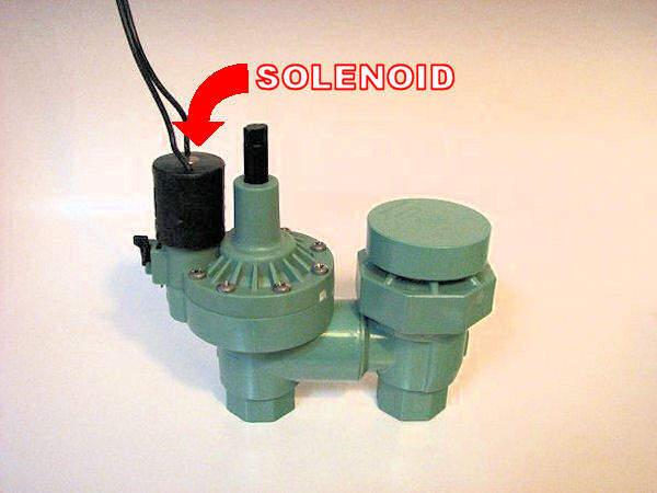
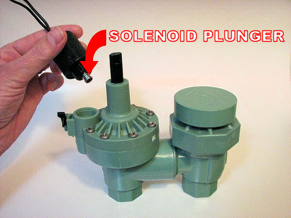
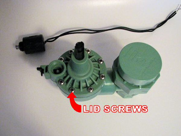
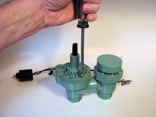
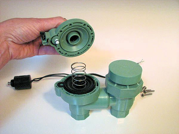
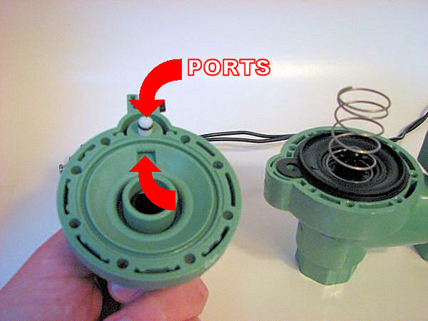
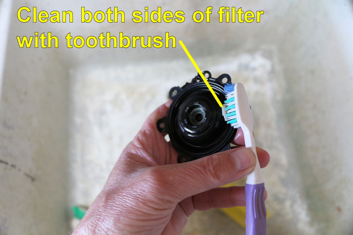
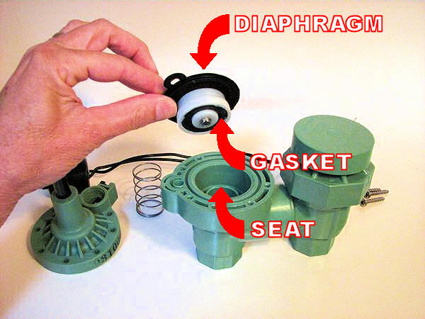
Lawn Sprinklers Dry Spots in Lawn
=======================
Troubleshooting Dry Spots
See the glossary on my web page for an explanation of any words or
terms used below that you don’t know. Example; if your not sure what
the difference between a lateral pipe and a mainline is, look up
those words. https://www.irrigationtutorials.com/glossary.htm
Check the valves to be sure they are fully opening. First, make sure
the flow control setting (if there is one) on the valve is in the
full open position. Next, manually open the valve using the bleed
screw or the open/close lever on the valve. Does the sprinkler
system work better? If so either the valve is bad, the controller is
bad, or the wires are bad.
Get three of the standard box-shaped 9 volt radio batteries (the ones
with the snap connections on the top). Make a “battery chain” by
snapping all three of them together end-to-end. This gives you 27
volts (9×3) between the unattached end terminals. That’s enough to
power the valve. Disconnect the valve wires at the point where they
are spliced into the wires leading to the controller. Cut out the
old splice and throw it away. Attach the valve wires to the open end
terminals of the battery chain. Does the valve fully open as it did
when manually operated? If so the valve is OK. If not the valve is
bad, replace it.
Next test the voltage output from the controller for each valve
stations. It should be at least 24 volts and over 0.5 amp. If you
don’t have the equipment to load test the controller for amperage you
can remove the controller from the wall and take it out near the
valves. Then run new wires from the controller to the valve wires.
Get a long extension cord so you can plug the controller in and then
turn on the valve manually using the controller. If the controller
is working correctly the valve should fully open. If the controller
checks out, then the wires between the controller and the valves are
bad and need to be replaced. If not, then the controller is bad and
needs to be replaced.
If the valves, controller and wires are ok, the problem is a
restriction in the piping. It could just be that the pipe is too
small, causing excessive friction loss. It could be sand or muck
buildup in the pipe. It could be a piece of metal, a rock, a rag, or
whatever stuck in one of the pipes. I’ve seen everything from fish to
toys in pipes.
Remove the last sprinkler heads and the sprinkler head riser on each
valve circuit. Cut the ell off the pipe where the last sprinkler was
connected to the lateral pipe. Install a new 45 degree ell on the
end of the pipe and a short length of pipe extending above ground.
The purpose of this is to get rid of the restrictions that a 90
degree ell and the riser create so you can get a good high velocity
flow to flush out the pipes. The outlet pipe needs to be above
ground to prevent dirty water from being sucked back into the pipes
after flushing. Turn the water on and allow the water to flush for
at least 5 minutes. After everything dries out, cut the flush outlet
off and reinstall the sprinkler. Test to see if that cured the
problem.
If not, there is probably something wedged tightly in the pipes
somewhere, so the next step is to isolate where that restriction is.
Prepare to get a wet while doing this test! You will need a 0-100
PSI pressure gauge. If you have rotor-type sprinklers get a “pitot
tube” to attach to the gauge. You can get one at an irrigation
store, call first, not everyone will have one in stock. The pitot
tube goes into the sprinkler nozzle so that you can measure the
pressure while the sprinkler is operating (doesn’t work for spray
heads, only rotors). If you have newer spray type heads with
industry standard female thread nozzles you can get an attachment
that allows you to install a pressure gauge on the sprinkler in place
of the nozzle. The attachment you need is a Rainbird #PA-80 adapter.
If you have male thread nozzles (Toro) or a non-standard nozzle
spray heads you will need to remove the the sprinkler head and attach
the pressure gauge directly to the sprinkler riser pipe where the
head was attached. This will require a few fittings and a short
length of threaded pipe.
Measure the sprinkler pressure at each sprinkler head location
starting with the last head and moving back toward the valve. Write
down the pressure for each sprinkler. If there is a large drop
between any two heads then that is where the problem is, drop down a
few paragraphs for instructions on how to fix the problem. If not,
then the problem is either someplace before the first sprinkler.
Tap into the mainline pipe just before the valve and install a tee on
the mainline and your pressure gauge. Turn on the valve and take a
pressure reading with one sprinkler circuit running. The pressure
should be around 5-10 PSI higher than the pressure you measured at
the first sprinkler after the valve. If it is more than that there
is probably something stuck in the pipe between the valve and the
first sprinkler. However, note that the pressure drop through
different brands of valves varies, so it might just be a high
pressure loss valve.
Next check the mainline for excess pressure loss. Tap into the
mainline right after the point where it connects to your water supply
and install your pressure gauge. Again, take a pressure measurement
while one of the valves is operating (it needs to be the same valve
as with the previous measurement). The pressure difference between
this point and the pressure reading you took at the valves should
generally be not more than 5 PSI. Again this varies dependant upon
the length of the mainline. If you have over 100 feet of mainline
the loss may be higher.
If you still don’t find an unusual pressure drop the problem is
probably just a poorly designed sprinkler system. The pipes are
likely all too small. There are no good solutions at this point
other than to trash the sprinkler system and start over. You can try
to divide up the larger valve zones into two new valves to reduce the
flow and thus the pressure loss. To determine if this will work,
remove and cap off half the sprinklers and test it. If it works
good, you can install a new valve and pipe to the capped off
sprinklers. But such approaches are usually less than satisfactory.
Consider seriously if it would be less work to just install a new
system that will work efficiently and correctly. My experience is
that you wind up paying more over the long run if you try to hack
together a cheap fix for a bad system.
If you think you may have an obstruction in the pipe:
Once you find the general location of the obstruction in the pipe
using the procedures above, the only solution is to start digging out
the pipe. Start by cutting out the fittings under the sprinklers,
most often if something is stuck in the pipe it will be wedged into a
fitting.
If you cut out a pipe and need to replace it I suggest using the next
pipe size larger than the old pipe for the new one. It will not hurt
the sprinkler performance to use a larger pipe and it may help it.
It is worth the cost of the larger pipe. Where the new pipe connects
into the old ones use a reducer fitting to change sizes.
===============================
How to Find Buried Pipes, Wires, and Valves
If you have an underground sprinkler system (drip systems too), somewhere out in your yard there are buried pipes, wires, and maybe even valves. But where are they? Sometimes they are above ground, so all you need to do is look around a bit. If not, then they aren’t visible because they are buried. (Big sigh.) You have perhaps the toughest problem there is in the irrigation repair business. There are no easy and inexpensive ways to find a valve, pipe, or wire. While this article addresses primarily valves, the methods for finding pipes or wires are basically the same.
Before we get going on how to find a valve let me make a couple of comments about what to do when you do find it.
Digging it Up
Once you find the valve you will probably need to dig it up. If you’re lucky it will be in a valve box and the box will not have been filled with dirt by some gopher. If there is a box be prepared to find critters inside the box when you open it! Use a shovel to pry the lid off from a safer distance. If the valve is not in a box, you need to be really careful when digging. Electric solenoid valves have wires attached to them that are very easy to cut with a shovel and very hard to repair once cut. Also if you hit the solenoid with a shovel you will probably break it and possibly break the valve as well. Even the valve body is easily cut as well as the pipe. So go slow and easy. Dig around the valve using a hand trowel. Better yet (I know this makes a mess!) you can use the stream from a garden hose with a patio cleaning nozzle on it to dig and use the water blast to loosen the dirt around the valve and wires. A plastic drink cup (ie; a McDonald’s cup) works good scoop out the muddy water and is unlikely to damage the valve.
If you cut or even nick the insulation on a wire, splice it back together using a water-proof splice kit made for underground wire splices. It is really important that the bare metal not be exposed to soil or water. Electrical tape alone will NOT work as a splice water-proofer! If the metal wire itself is not damaged you can seal the damaged insulation on the wire by coating the damaged area with several thick layers of PVC cement (glue). Let it dry then wrap the entire area tightly with plastic electrical tape, extending several inches beyond the damaged insulation. Then coat the tape with pvc cement. This is not the best solution, but it usually works.
If the metal wire is damaged (even if it is just partially cut) you need to cut out the damaged section and splice in a new section of wire. Use special water-proof splice connectors you can buy at any hardware store for ALL your irrigation wire splices and connections. Even ones above ground! If any water leaks into the splice it will corrode the wire. Even if the wire is not corroded through, the corrosion can block enough electric current to make the valve not open. If the wire breaks or corrodes it will be a major pain to find where the problem area in the wire is. You will probably have to replace all of the wire. You do not want to have to do that! Water-proof those splices. Got it?
I strongly recommend that if you splice or repair a underground wire you put a valve box over the repair rather than just burying it. Any splice or wire repair is going to be a likely source of future problems. The box will help protect it and will allow you to more easily locate the splice/repair in the future if you should have problems. If you can’t put a box over it put something else there that will help you locate it, like a metal tent stake driven fully into the ground at the splice location. You can find the stake with a metal detector. Make a note diagramming the location of the splice/repair and put it in the irrigation controller case.
Be Prepared to Replace the Valve
There is a pretty good chance that if you can’t find the valve you will need to replace or repair it when you do. That’s just how the odds stack up. If the system is in such bad shape that you can’t find the valves, usually the valves are in bad shape also. So prepare yourself now for that expense and effort.
Box It!
Once you find your valve, put a valve box around it! Irrigation valves are often marketed as “direct-burial”, but as you now know (or will soon discover), finding one that has been buried directly in the dirt is very difficult. It doesn’t need to be a big fancy box, they make nice little inexpensive ones that work fine. Even a used plastic bucket or gallon size paint can flipped upside down will make a decent temporary valve box until you can afford something better. It just isn’t a good idea to bury a solenoid valve directly in dirt. Besides the problem of finding it later, burying it can also make it fail faster. Plus you are a lot more likely to damage a valve buried in dirt when you dig it up for repairs. And all valves are going to need to be repaired someday! So put those underground valves in boxes, and while you’re at it, put 4″ of gravel under the box! The gravel keeps gophers from digging into the box from underneath and filling the box with dirt. You can buy a small bag of gravel at most home improvement stores. (Decorative rock works also, especially that rough surface lava rock.) You might also want to measure and write down where the box is located as measured from a couple of fixed locations, such as a house wall or fence. That helps you find it if grass grows over the top of it… if you don’t lose the measurements!
OK, time to get to work.
How to Find a Buried Valve
1. Start by trying to figure out what the most likely place is where the valve would be installed. To do this you need to try to “get inside the head” of whomever originally installed the system. This helps cut down the “search area”. Do you know where other valves are in the yard? Are they each inside the area they water? If so, the others are probably inside the area they water also. Are they grouped together? Then the others may be nearby. Maybe there is a pattern to the placement of the valves, all on one side of the yard perhaps, or all in a row? If you don’t know where any of the valves are, you still know a pipe takes water to them. Find where that pipe connects to your water supply. Now try to figure out which way the pipe goes from there. Sometimes if you look real close you can see a slight indentation in the soil where the trench for the pipe was dug. Another tip, the grass is often just slightly greener where the trench was dug. For lawns, if you mow the grass short and look across the surface you can often see slight “troughs” where the trenches were dug and the soil has settled.
If you have the original plans for the sprinkler system they may help you find the valves, pipes and wire locations. If this is a commercial irrigation system the local building inspector or planning department may have a copy of the plans. However, even if you do have the plans, chances are the valves aren’t located where the plans show them. So I wouldn’t waste too much time looking for plans. In 35 years of practice and thousands of irrigation systems, I seldom saw the contractors install the valves exactly where they were shown on my plans. Even when I required my contractors to label and dimension the valve locations, I often discovered they just made up the dimensions!! At best a plan might give you a hint as to where to look.
2. If the valve you are looking for is an electric valve that actually still works, try turning the valve on and see if you can hear the solenoid buzzing or water whizzing through the valve. Try using a mechanic’s stethoscope placed on the ground to listen. Or cut the bottom out of a paper cup, place it upside down on the ground, and put your ear over the top. Do this late at night or in early morning to reduce background noise and make it easier to hear. Note; if the neighbors see you they will think you’ve lost your mind!
3. Try a metal detector if you own or can borrow one. I’ve honestly never tried this, but some people tell me it works, and it seems logical. Most valves have at least a little metal in them, although the cheapest ones have very little. The solenoid on an automatic valve has a bit of metal in it also. If you have, or can borrow, a metal detector you may be able to locate the valve or the wires with it. If the valve or wire are buried deep, a low cost metal detector will probably not find them. In my opinion the chances of success using a metal detector probably are not good enough to make it worth the expense of buying one. But if you have one or can borrow one, why not try it? I’d love to get your feedback on use of a metal detector if you try it!
Try following the pipe to the valve using a metal detector. According to reader James P. you can trace the location of a pipe using a metal detector and a “fishing tape” (aka; draw wire or draw tape). A fishing tape is a long tape used by electricians, they inserted the tape into conduits to pull wires through them. The tape needs to be metal or at least it needs to have a metal section at the end of the tape that you can detect. You need to cut the pipe open, then you insert the tape into the pipe. A high-quality metal detector (he warns the cheap ones aren’t powerful enough) can then be used to trace the location of the end of the tape from the ground surface. You may have to follow the route in sections depending on the length of the tape. Also if there are any tees or ells in the pipe the tape will not easily slide past them, so you may need to dig a few potholes to cut into each new section of pipe after a tee or ell. Repair the sections of pipe you cut out to insert the tape using repair couplings or compression couplings. You will find these at any hardware or home improvement store.


4. Use a valve chatterer. This won’t work if the wires to the valve are cut or broken. So if you’re trying to find an automatic valve that won’t open, a chatterer is not likely going to help. A chatterer is a electrical device you put on the valve wire that makes the valve rapidly turn on and off. The result is that some brands of solenoid make a loud clicking or chattering sound that will give away it’s location. Unfortunately some valve brands don’t make much noise at all. And the deeper the valve is buried, the harder it will be to hear it chatter. Most irrigation pro’s have valve testers that include a chatter function along with other testing tools. These are handy tool for diagnosing valve electrical problems, but tend to be priced beyond what is justifiable for a homeowner to buy. (See ads for typical chattering devices at right. Also see my review of the Armada Pro48, which is the one I use.) To use a chatterer you disconnect the valve’s wires from the controller/timer and hook them up to the chatterer device. Turn the chatterer on and the valve should rapidly open and close and create a noise. Just like with listening for the water running through the pipe, you will have to go out in the yard and listen for the chattering, and it will help if it is during a quiet time of the day.
Make your own chatterer. All you will need is three 9-volt batteries and a friend with dexterous fingers. Someone who texts a lot on their phone is perfect! Start by making a valve actuator. Here’s how to make one out of three 9-volt batteries. To chatter the valve simply attach one of the valve wires to one terminal of your home-made actuator and tap the other wire against the other terminal of the actuator. Tap the wire at one second intervals. It doesn’t matter which wire goes to which terminal. The valve should turn on and off with each tap and make a clicking sound. I don’t recommend tapping the wires on the controller/timer terminals to chatter the valves. If you slip up while trying to tap the wires against the terminals and short circuit the wires you can damage the controller/timer. Destroying an expensive controller will ruin your day!
5. Water Dowsing, aka; water witching. This is a method of finding a water filled pipe by walking slowly while holding a branched stick or a couple of bent wires in your hands. I won’t try to explain how to do it, you can look it up if you want to try it. I’ve never witnessed it done successfully firsthand. But I have met several people over the years who have either seen it done successfully or done it themselves successfully. This includes people I trust, so I’m not in doubt of their claims. Did they see or do what they thought they did? The answer to that thorny question I will leave to you to decide!
OK, the science behind dowsing is very shaky- at best. Most explanations I have heard are that those with the talent are able to read subtle signs on the ground surface that indicate the location of water or the pipe. They then subconsciously transfer that information to the movements of the sticks, like a Ouija Game. Maybe. But most of those I’ve talked to say that the force on the stick/wire is very strong and not likely to be from anything subconscious.
Everyone I know who claims dowsing works or that they have the ability to do it IS an expert who has worked in the industry many years. I can tell you that with 35 years of experience I can often look at an irrigated area and tell you where the pipes are with reasonable accuracy. No sticks needed. Just lots of experience looking at irrigation systems, and hints like those I’ve already covered, dips in the ground surface where trenches have settled, areas that are greener than others, etc. At any rate, I don’t want to get into any arguments over dowsing. I present it as an option that many believe works. If you can find someone with the talent, they may, or may not, be able to help you find the pipes, valves, or wires (yes, some dowsers claim they can find wires too!)


6. Use a wire locator (aka; wire tracer) device. This is how the pros do it, but if you notice the cost of a wire locator (ads on right), you will probably find that if you are a homeowner it is not within your budget! Some tool rental places, especially those that cater to professional contractors, have wire tracers they rent. (Sprinkler Warehouse rents wire tracers using overnight shipment.) You use a wire tracer to follow the path of the wires to the valve, starting at the controller/timer. Again, if the wire is broken you may not be able to follow it (although the better units can even jump the signal over small wire breaks. However, it will find the location of the break so you can repair the break in the wire. Then you can continue tracing the wire to the valve– or the next break in the wire! ) Also be aware that it takes a bit of practice to use a wire tracer, but it can be mastered in a few hours. The way it works is that you attach a signal generator attached to the valve wire. Then you use a receiver that senses the signal. The receiver beeps when you are near the wire. A word of warning on wire tracers. You need a tracer with a signal generator that is powerful enough for the sensor to be able to pick up the signal through 24″of dirt depth. While most residential irrigation wires are not installed that deep, they are supposed to be! The wire tracers made for use by electricians to find wires in house walls are not powerful enough to detect buried wires, even if they are only a few inches deep. I have one made for detecting wires in walls, that also lists irrigation systems as a suitable use, and it will NOT detect wires buried even 1″ below ground!!! So before you spend money, make sure the device is suitable for wires that are buried underground.
Hey, do you know someone who works as a line-person for a phone or cable company? They may have access to a wire locator since they often use them for repairs. Maybe this weekend they might trade a few minutes of their time for a couple of beers? hmmmm?
Now for the “this is a lot of work” solutions! Start with a trip to the store to stock up on Advil and Ben-Gay.
7. Probing for valve boxes. Before you try digging, first try a shallow probe for valve boxes. If valve boxes were placed over the valves when the system was installed, they are probably just below the surface. Often the only reason you can’t see them is that grass grew over the top of them. A pitch fork is ideal for probing for the boxes, just gently stab the ground until you hear the clunk of a fork tine hitting the plastic box top. If you don’t have a pitch fork a metal yard rake works for some people (others can’t get the motion right to plant the rake tines through the grass), a stick with a long nail-spike on the end of it works good to probe the ground, and last resort is to use a screwdriver on your hands and knees (ouch!) Again, use logic to figure out the best place to start probing.
8. Probe or dig to find the pipes. (My back is hurting just from writing about it.) If no valve boxes were used, then you will need to probe deeper. Now, just to warn you, it is highly likely you will cut or break a pipe or wire while you are doing this. So just be prepared for that as a cost of the process of finding the valve. OK. Fortunately installers who don’t use valve boxes also tend to not bury the pipe and valves very deep, cause they’re lazy and cheap. Normally the pipe from the water supply to the valve is buried deeper than the pipe from the valve to the sprinkler heads. (This pipe is called the “mainline” and is supposed to be at least 18 inches deep!) Plus the wires normally are thrown in the same trench with that mainline pipe going to the valves, and you don’t want to cut or nick a wire with a screwdriver blade. So it’s best to start at a sprinkler head and work backwards toward the valve. Use a long blade screwdriver to gently probe for the pipe around the sprinkler. Try to pick a sprinkler head you think might be close to the valve. If you can turn on the sprinklers, the one closest to the valve will often come on slightly quicker than the others, and have more pressure, so it will have a more “powerful” sound and forceful spray when it is operating. Be gentle when probing, don’t break or pierce the pipe! Once you find the pipe keep probing and follow it back to the valve. If the ground is really dry and hard, you might want to water it to soften it up first. As you follow the pipe consider marking the pipe locations on the grass or dirt using some of that special marking spray paint or the little sprinler flags they sell at irrigation supply stores. Marking the pipe location will help you track where you found pipes (ie; this could be a multi-day project!) Tip; draw yourself a diagram of the sprinkler pipe locations for future use as you find out where the pipes are!
What if you can’t find the pipes with a screwdriver? Well, in that case it’s time for a shovel. Have fun digging up the yard! 🙁
Dealing with Small Pipe Leaks in Sprinkler and Drip Systems
Small mainline leaks can be a really tough problem to deal with. A master valve will cure the symptoms for a while. The master valve should be the same size as the other valves unless you run more than one valve at a time. It is installed at the connection point of the irrigation system to the water supply. You will need a irrigation controller that has a master valve circuit on it (sometimes called a “pump start circuit”, the two are the same thing.) You wire the master valve to the master valve circuit on the controller using two wires, just like any other valve. It will then open whenever any other valve on the system opens to irrigate. When the irrigation is complete, the master valve will close which will relieve the pressure on the mainline, stopping the leak.
However this does not cure the leak, which will continue to get worse as the water erodes the pipe around the leak and the hole gets larger. Also, master vales come with their own unique problems. With a master valve the leak may (depending on it’s size and location) drain the water out of the mainline after each irrigation, which will cause new problems. The system will spit air each time it starts up and make lots of noise. This also weakens the pipe over time due to the stress of refilling with water at the start of each irrigation. The sprinklers will also not run efficiently for the first minute or so as the air is expelled. Next, dirt may be sucked into the mainline through the leak hole when the system depressurizes. The dirt can then get into the valves and sprinklers causing them to fail. Finally, pressurizing and depressurizing the mainline causes it to wear out earlier than normal. (Think of inflating a balloon and releasing the air over and over. It wears out the plastic and then the balloon pops. Same with your mainline.) How much impact this has is a matter of debate in the irrigation industry, the difference might be that your mainline only lasts 15 years rather than 20. Again, it varies depending on your system, the higher your water pressure the more likely damage will occur.
Finding a leak can be very difficult, there is no easy way that I know of. The only way I know of to find a leak is to visually inspect for it. This is hard with buried pipe. First inspect for leaks around the obvious places like the threaded connections to the valves. Threaded joints are by far the most common locations for leaks. Clean and thoroughly dry any water off of the connections with a towel, wait a few minutes, then wipe the connection with a paper towel and see if the paper gets wet, indicating a small leak.
You may be able to hear the leak if it is fairly large, but a slow drip will not make enough noise. You can make a “stethoscope” to listen with using a cardboard tube like the ones used as used for wrapping paper.
Also you can look for mud or soft wet dirt around the leak. Try probing the ground with a long screwdriver, looking for soil that is wetter than other areas. Then start digging. You may have to just wait until it gets bad enough to become visible.
Installing a Pipe under a Driveway or Sidewalk
The easiest “do-it-yourself” way to get a pipe under pavement is
hydraulic boring. Take the pipe you want to place under the driveway
and connect a sweeper nozzle (used to hose off driveways) to one end
and a hose to the other. Glue “hose thread” adapters to the ends of
the pipe to connect the nozzle and hose (you’ll need one male and one
female adapter). Dig a trench on one side of the driveway and an
exit hole aligned with the trench on the other. Turn on the water
and shove the pipe under the driveway. The water blast from the
nozzle will dig a hole as you push the pipe under. Be prepared to
get very dirty and wet! After the pipe is under the driveway, remove
the nozzle and hose, and cut off the adapters. You now have a pipe
under the driveway. The hole around the pipe will be somewhat larger
than the pipe, which can cause a problem with asphalt driveways. If
the soil above the hole collapses, the asphalt will give way under
the weight of a car. If you want to chance it with an asphalt
driveway, make sure the pipe is 18″ deep under the asphalt, so there
is more soil to support the weight. You can dry to push concrete
into the hole around the pipe to fill it in and give more support,
but this is difficult to do.
Boring tools are available which work better in rocky soils and under
asphalt. These tools “drill” a hole using a bit. You can rent them
at some rental yards, but in most cases you are better off hiring
someone to do it for you. These guys have boring tools that can
drill over 100′ and even can make minor turns as they bore. So they
can get a pipe from the front yard to the back under a sidewalk or
patio. When boring under asphalt, most boring companies will install
a sleeve as part of the boring work to support the surrounding soil
and prevent the asphalt from settling. You then push your irrigation
pipe through the sleeve. Look in the yellow pages under “Plumbing”
for companies that do “trenchless” installation or “boring”. If none
list those services in their ads, try calling a professional plumbing
supply store and ask if they can give you a referral to a company
that does boring. Often these specialized companies are just one guy
with a boring machine and don’t advertise. They tend to be pretty
busy because of all the communications cable installation going on
with the Internet expansion. Most telephone cables are now bored
into place to minimize damage to roads and property.
Sometimes for asphalt driveways you will need to “sawcut” a trench
through the driveway, then repair the driveway after the pipe is
installed. For companies that saw asphalt look in the yellow pages
under “Concrete Breaking, Cutting & Sawing”.
Hope that helps!
Regards,
Jess
How to make an Organic Pre-filter for a Pond or Stream Irrigation Water Supply
Pre-filters are used when pumping water from a pond, or a slow moving stream or river. These instructions are based on a 20 GPM water supply, if you need more water you will need to use a larger pipe and hole, or manifold multiple pipes together. This is a very basic outline of what is required, you will obviously need to adapt it to your situation.
Dig a 3 foot deep 10 foot long hole in the stream or pond bed . Next make a intake manifold, it is just a piece of 2″ SCH 40 PVC pipe with a cap on one end and your intake pipe connected to the other end. You then drill one hundred each, 3/8″ diameter holes in the manifold pipe to allow the water to flow into the manifold. Put a plastic liner on the bottom of your hole. Now put 6″ of 3/4″ diameter gravel in the hole. Then lay the intake manifold in the hole on the gravel and pack another 12″ deep layer of 3/4″ gravel around and over it. On top of that you place another 18″ deep layer of 3/8″ gravel.
The gravel acts as a “pre-filter”. As the water moves slowly down through the gravel layers to the intake manifold the sand and much of the algae gets trapped in the gravel. This is generally enough to protect the pump. You still need a filter after the pump and it still might need to have a auto-flush mechanism.
To slow down a fast moving small creek to allow pumping water from it the classic method is to create a small, low, dam using sand bags. Not only is the use of sand bags easy, it is also temporary and the sand bags can be removed seasonally if desired.
Remember that in most countries there are lots of rules and regulations that apply to disturbing stream beds. In the USA, at a minimum, you should contact the US Fish and Game Department and EPA for advise. There are probably also State and Local regulations as well. The fines for violating rules or regulations can be very extreme! Make sure you get a ll required permits.
Getting rid of Gophers
Most pros poison them, but we have lots of pets in our area so I don’t like to use poisons. I trap them with a gopher trap (the kind with spring loaded spikes that drive into their head to kill them, it’s gruesome but very effective.) Place a rope on the trap and tie the other end to a stake. Dig a 12″ diameter hole to expose a tunnel, then slide the trap into the tunnel. Place some fresh grass clippings in the hole behind the trap as bait. Cover the hole with a piece of plywood and place dirt around the plywood to seal out all light. The next morning remove the plywood and pull on the rope to remove the (hopefully dead) gopher.
Pressure Loss in Sprinkler Risers
Q. How do I calculate sprinkler risers losses in a sprinkler zone where the risers are extra long, 3 ft or more above ground? I have 10 risers in a zone for my proposed sprinkler irrigation system.
A. If you are using my Sprinkler System Design Tutorial and a standard riser of the recommended size, then you don’t need to worry about pressure lose in the riser, the tutorial has friction loss for the risers built-in to the formulas it uses. So you can ignore the riser pressure loss. Some standard risers are shown on the page on Sprinkler Risers in the Irrigation Installation Tutorial. The recommended size for a riser? In most cases it should be the same size as the threaded inlet on the sprinkler. But please actually read that page on risers, as there are some exceptions to that rule for certain types of standard risers!
Non-Standard Risers:
OK, I realize that didn’t answer your question, you are asking about a non-standard riser that uses a long pipe to hold the sprinkler high above the ground. In that case you must calculate what the friction loss will be in the longer-than-normal riser pipe. (In this case that would be the 3 ft long pipe you described in your question above.) To do that you simply use the same friction loss spreadsheets that you use to calculate the friction loss in any other pipe. Just use this link to get the proper spreadsheet from my website for the type of pipe you are using. Then open the spreadsheet and on the first line enter the pipe size, GPM of the sprinkler you will install on the riser, and the length of the riser. Enter an error factor of 1.4 rather than the default 1.1. This is because even your “longer” riser is shorter than the typical pipe length that the default error factor is based on. Now read the friction loss. That’s it, you have the friction loss for your non-standard riser! Don’t worry about the fittings like ells and couplings that are part of the riser, that is part of what the error factor is compensating for.
When adding the riser friction loss into the total friction loss calculations for your whole sprinkler system, just add in the loss for a single riser. Use the friction loss value for the riser that has the highest friction loss. (This is most likely the one with the highest GPM sprinkler, or it may be the longest riser if you have different riser lengths. You may have to calculate the friction loss for several different risers to figure out which of them has the highest loss.) Why do you add in the friction loss for only one sprinkler, rather than the combined loss for all of them? Because as a single drop of water goes through the sprinkler system it only goes through one sprinkler, not all of the sprinklers. You have to think about the water as a collection of millions of drops, not as one solid body. So the pressure loss is what a single drop would experience as it travels through the system. As a drop of water enters the sprinkler system it travels through a water meter, lots of pipe, a valve or two, then it finally blows out through a single sprinkler onto the landscape. The pressure loss calculation for the whole sprinkler system is determined by what the worst case pressure loss values would be for a single drop of water traveling through the sprinkler system.
OK, so you calculated the friction loss, but what if it is a really high value, or maybe the calculator complained about the velocity being to high. In this case you need to use a larger size pipe for your riser. For the velocity in a riser you can go all the way up to the 7 ft/sec maximum without too much risk. Velocities in the marginal “use caution” zone are generally OK for risers. High velocity in a riser will seldom cause a water hammer problem, unless you are using a special type of sprinkler that has a solenoid valve built in to it. Those sprinklers are called “valve-in-head sprinklers”, they are very expensive, and are mostly used for golf course greens.
Sprinkler Buddy Sprinkler Head Indicator Review

The Sprinkler Buddy is a cone shaped plastic collar that fits around a sprinkler head to prevent grass from growing up next to it. It serves two purposes, the first purpose is to keep grass from growing over the sprinkler head, thus make the sprinkler location obvious in the lawn. When using heavy power mowers this allows you to mow over it while avoiding hitting and breaking the sprinkler heads. The old standard method of keeping sprinklers visible is to trim around them each week with a line trimmer to remove the grass around them. Obviously this is a lot of work that is not needed when the Sprinkler Buddy is installed around the sprinkler. A second use for the Sprinkler Buddy is as a sprinkler head stabilization device. According to the manufacturer, the wide cone shape helps keep sprinklers in an upright position. Another advantage of the Sprinkler Buddy that isn’t heavily promoted by the company is that it keeps tall grass away from sprinklers with low pop-up heights, again reducing the need for frequent grass trimming around the sprinkler head. The Sprinkler Buddy is made to fit on all pop-up sprinklers, both the smaller body spray types and the larger residential rotors (up to 2.5″ diameter, and maybe a bit larger.) It is a product of RyRo, Inc. of Florida, USA.

Installation:
The Sprinkler Buddy is made of a semi-rigid, UV protected, plastic material that is soft enough to cut with a pair of scissors, but rigid enough to maintain it’s shape. To install you start by cutting away the grass from around the sprinkler in an area just large enough to fit the Sprinkler Buddy into. Next, the sprinkler head is unscrewed from the pipe (the proper name for this pipe is a “riser”) to remove it. Using scissors, simply cut slits in the Sprinkler Buddy base that are large enough to allow your sprinkler to slide into the bottom of the Sprinkler Buddy. In a few situations you may also need to trim the edges of the Sprinkler Buddy to custom fit it to unique situations, for example if the sprinkler is very close to a sidewalk or wall. Finally the Sprinkler Buddy is pushed onto the sprinkler head, and the head is screwed back onto the pipe. A set of complete installation instructions are on the Sprinkler Buddy Website.
Test Results:
I installed two Sprinkler Buddies into a professionally maintained condominium complex in Portland, Oregon during the summer of 2011. The Sprinkler Buddies were installed per instructions over existing brass sprinklers, one was a flush mounted no-pop-up spray head, the other was a low pop-up with gravity piston retraction. (I need to insert a disclaimer and warning here. Both these sprinklers are older types, they were state of the art in the ’50s and ’60s, but are still found on a lot of older sprinkler systems. While still available for sale in stores, these heads are an antiquated design that are high maintenance and water wasters. As a professional my first recommendation for these sprinklers would have to be that they be replaced with new plastic-body pop-up type sprinklers with at least a 4″ rise height. See my recommendations and reviews of sprinkler heads.)
The Sprinkler Buddies immediately performed as expected, they held back the grass that had previously interfered with the sprinkler’s spray patterns, allowing for better water coverage. The maintenance caretaker also reported that he no longer had need to trim the grass back around those heads as he does with all the other heads on the property. He did note that periodically some bermuda grass would grow up between the sprinkler body and the sprinkler buddy. This appeared to be an infrequent issue that might require a check of the sprinkler once or twice a year in order to remove any grass growing inside the Sprinkler Buddy.

The Sprinkler Buddies were left in place for the winter and rechecked in the spring and again in the summer of 2012. Upon examination in spring we found that the Sprinkler Buddies had each filled with leaves and pine needles over the winter. The leaves and needles were easily swept out using an old broom, and an examination showed no damage from frost or snow to the Sprinkler Buddies. Further, no grass was growing inside either of them and no grass trimming was needed around them before restarting the sprinklers. By way of contrast, we could not even locate the other sprinklers in the lawn that did not have the Sprinkler Buddies. Despite having the grass trimmed well away from them in the fall, these sprinklers were now completely covered with grass that had grown during late fall and early spring while the sprinklers were shut down for the rainy season. We had to turn on the sprinkler system to locate the other sprinklers and then mark their locations so the grass could be trimmed away from them.
Conclusion:
The Sprinkler Buddy worked as promised. It clearly marked the sprinkler locations making them very visible, and it looked attractive if you are into that edged sprinkler look. While not my thing, I have met a lot of people who love the look of a clean cut edge around their sprinkler heads, and for them the Sprinkler Buddy will be something they love. It will create a near perfect edge of uniform size around each sprinkler head. In my tests the Sprinkler Buddy was also very effective at reducing maintenance at the sprinklers where we installed it, saving about a minute a week in grass trimming effort for each sprinkler. It was also a huge labor saver at the spring season sprinkler system start-up, saving about 10 minutes of time per sprinkler (for sprinklers without the Sprinkler Buddies the caretaker had to turn on each valve circuit, located and flag the sprinklers, then return later with the string trimmer to trim away grass from them.) The caretaker was able to mow over the Sprinkler Buddies with his rotary mower without damaging them.
On the minus side the Sprinkler Buddies were a bit harder to install than I expected, mostly because I needed to remove the sprinkler heads and they were rusted in place. Some people have stated that they successfully have installed the Sprinkler Buddies without removing the sprinklers. I did try this and I was not successful at installing the Sprinkler Buddy to my rather high quality standards (ie; I was able to get it on but I didn’t like the way it looked when finished and it wasn’t nearly as stable.)

Caveat:
The Sprinkler Buddy is made to cure a problem that you really shouldn’t have. (Unless you are one of those people I mentioned who like the look of a neat cut-out area around each sprinkler head, or you just want to be able to see all your sprinklers all the time.) A properly designed sprinkler system should be able to take a direct strike on a sprinkler head by a heavy mower without any damage. Properly selected sprinkler heads should also utilize pop-up risers that allow the nozzle to rise well above the grass level so that grass does not interfere with the water spray pattern. Almost all sprinkler bodies now are constructed of high-impact plastic, engineered in a way that, when properly installed, can take the shock of being hit by a large rider mower wheel without damage. However for this to occur the sprinkler must be installed on the proper type of riser that allows them to both absorb the shock and stay in an upright position. This website has suggestions for identifying both quality sprinkler heads and the proper risers to use. Unfortunately switching over a older sprinkler system to utilize new sprinkler heads and risers can be time consuming and expensive. The Sprinkler Buddy is a good temporary fix for these older systems that will reduce maintenance time and costs until such time as a proper repair may be made. A wise approach would be to use the maintenance cost savings created by the Sprinkler Buddy, and save back that money to fund a future replacement of the sprinkler heads and risers.
Where to Get Answers to Specific Irrigation Questions
Irrigation Sprinkler Head Selection
Types of Sprinklers:
There are a lot of sprinkler head brands and types out there. So how do you decide which one(s) to use? This page will break down the types of heads available and what each type is best suited for. We’ll look at the advantages and disadvantages of each type as well as issues such as brass vs. plastic construction.
To start, sprinklers heads are divided into two types based on the method they use to distribute the water, called spray heads and rotor heads.
Spray Heads:
More properly called “fixed spray heads” these are the small heads that spray a fan-shaped pattern of water. Think of a shower nozzle. Most use interchangeable nozzles installed on the sprinkler which determine the pattern (1/2 circle, full circle, etc.) and the radius of the water throw. Some specialty patterns are available for long, narrow areas. Spray heads are spaced up to 18 feet apart. There are some brands that promote radii up to 20 feet, but I’ve had really poor experiences with those. Spray heads need between 20 and 30 PSI of water pressure to operate properly so they are the best choice if you have low water pressure.
Rotor Heads:
Rotor sprinkler heads, often just called “rotors”, is the term used to describe the various sprinklers which operate by rotating streams of water back and forth over the landscape. The example which most people are familiar with is the “impact” rotor sprinkler (often improperly called a “rainbird*”) which moves back and forth firing bursts of water. You probably know this sprinkler best for the distinct sound it makes when operating– tooka, tooka, tooka, tic, tic, tic, tic, tic, tooka, tooka, tooka, etc… The impact rotors are rapidly being replaced now by gear driven rotors which are much quieter, lower maintenance, and much smaller in size. These gear-drive rotors have one or more fingers of water which move silently across the landscape. The prettiest of these are the “multi-stream rotors” where multiple streams of water rotate over the landscape one after the other like rotating spider legs. Rotors can be spaced from 15 feet to 65 feet apart. There are rotors available that can be spaced farther apart than 65 feet but I don’t advise using them in most situations, even golf courses are moving away from using them due to problems. Most rotors require a lot more water pressure to operate than spray heads. Here’s a rule of thumb, “The water pressure at the rotor head in (PSI) must exceed the distance (feet) between the heads.” (Known as Stryker’s Rule, admittedly that’s a little ego stroking on my part, but I really did write the rule!) Thus if you want to space rotors 35 feet apart you will need 35 PSI of pressure at the rotor. More on this later. The small rotors most often used for residences work best at 25 to 35 foot spacings.
Note: If you have chosen to use the Prescriptive Standard the maximum spacing you can have between rotors will be 30 feet. This is due to the 30 PSI sprinkler pressure used by the Prescriptive Standard.
* Rain Bird® is the name of a sprinkler company and is a registered trademark. The Rain Bird company makes many different types of sprinkler heads, including impact rotors. They also make a full line of other irrigation products.
Rotary Nozzles: A new type of miniature rotor has been introduced in recent years. These are often called rotary nozzles. The first brand on the market was called the “MP Rotator”, and several other similar products quickly became available from other companies. Rotary nozzles are a very small turbine-driven rotor mechanism that is the same size as the standard nozzle on a spray-type sprinkler. Thus they can be installed onto the smaller, and less expensive, spray head pop-up bodies. These rotary nozzles have a radius generally between 15 and 30 feet. The exact distance depends on the model. They all use multiple streams of water that rotate around the nozzle and look like rotating spider legs. Some research indicates these rotary nozzles are more efficient than standard spray heads and result in lower water use. So far they have performed well overall, but beware of recently introduced models as this is tricky technology and new products may have a lot of “bugs”.
Guide to Selecting the Right Sprinkler Type:
Which to use, sprays, rotary nozzles, or rotors? Here are some questions to guide your selection.
- Is your water pressure less than 45 PSI static? If so you should consider using sprays or rotary nozzles.
- Is the area less than 16 feet wide? Then you should consider sprays or short radius rotary nozzles.
- Areas between 16′ and 25′ wide are good candidates for using rotary nozzles.
- If the area you want to water is greater than 25′ x 30′ in dimension standard rotors are likely the best solution.
- Is the edge of the area to be watered curved? If the edge has sharp curves (less than 20′ radius) then rotors will have difficulty watering the edges without over spraying them. This may not be an issue depending on what is beyond the edge. If the area beyond the edge should not get water on it (like a sidewalk, patio, driveway, road, or structure) you might want to consider a smaller rotary nozzle or spray-type sprinkler.
Installation Issues related to Head Selection:
Rotors are spaced farther apart and require less pipe and trenches, but they also cost much more per sprinkler. Systems that use rotors, and to a lesser extent rotary nozzles, are easier to install due to less trenches to dig and back fill.
Cost Issues in Selecting Type of Sprinkler:
Surprisingly, regardless of the type of sprinkler you use, the cost per square foot of area irrigated comes out about the same (assuming proper design.) When using rotors there is less pipe and trenches, but the rotors themselves cost more. Spray heads are less expensive to buy, but they require more pipe, more trenches (labor cost), and more valves. In the end, the price really comes out pretty close either way.
![]() Note: If your “design pressure” is less than 40 PSI standard rotors will not work properly, DO NOT USE THEM. (That’s Design Pressure, not the pressure at the sprinkler head.) See the section “Measure Your Water Supply“. If you have a well and pump you must have your pump-on setting adjusted to no less than 40 PSI if you plan to use rotors. A “40-60” setting is typical. Contact your pump company for assistance.
Note: If your “design pressure” is less than 40 PSI standard rotors will not work properly, DO NOT USE THEM. (That’s Design Pressure, not the pressure at the sprinkler head.) See the section “Measure Your Water Supply“. If you have a well and pump you must have your pump-on setting adjusted to no less than 40 PSI if you plan to use rotors. A “40-60” setting is typical. Contact your pump company for assistance.
![]() If you are unsure, try using rotors in your design. If they don’t work out well, then erase them from your plan and try rotary nozzles. In may situations the best option may be to use rotors in the large areas, and spray heads or rotary nozzles in smaller or more narrow spaces. So you may have a mixture. This is OK, but there are some things you need to be careful of when mixing different types of sprinklers. The first is that each type must be on a separate valve circuit. More on this later in the tutorial. The second is determining how to space the heads where they meet each other. For example, if you have a 30′ radius rotor next to a 15′ radius spray head, how far apart should they be from each other? There are many different schools of thought on this, but my general recommendation is to split the difference. In this example put them 22′ apart. Yes, the rotor would over-shoot the spray head by a considerable distance. But if you put them 30′ apart you will get a distinct dry spot between them.
If you are unsure, try using rotors in your design. If they don’t work out well, then erase them from your plan and try rotary nozzles. In may situations the best option may be to use rotors in the large areas, and spray heads or rotary nozzles in smaller or more narrow spaces. So you may have a mixture. This is OK, but there are some things you need to be careful of when mixing different types of sprinklers. The first is that each type must be on a separate valve circuit. More on this later in the tutorial. The second is determining how to space the heads where they meet each other. For example, if you have a 30′ radius rotor next to a 15′ radius spray head, how far apart should they be from each other? There are many different schools of thought on this, but my general recommendation is to split the difference. In this example put them 22′ apart. Yes, the rotor would over-shoot the spray head by a considerable distance. But if you put them 30′ apart you will get a distinct dry spot between them.

Basic Body Styles:
Pop-Up Style Sprinklers:
Pop-up style sprinklers are installed with the sprinkler body below ground. A portion of the sprinkler, appropriately called the “riser”, rises up out of the ground when the sprinkler is operating and then retracts back below ground when not in use.
Shrub Style Sprinklers:
Shrub style sprinklers are installed above ground on top of a section of pipe. Read the warning below!
Which style to choose? In most cases you will want to use pop-up style heads, even in shrub areas. Pop-up sprinklers are more expensive to buy, but with shrub sprinklers you also need to include the cost of the extra section of pipe needed to hold the shrub sprinkler above ground. In fact, in recent years mass production of popup style sprinklers has lowered their price, while increases in pipe costs have made shrub style sprinklers overall more expensive.
![]() Many people are injured each year when they trip over, or fall onto, shrub style sprinklers. For shrub and ground cover areas pop-up sprinklers are available with pop-up heights of 3″, 4″, 6″ and 12″ above ground. A few brands are available with lower pop-up heights, but be warned that lower heights often cause problems. I recommend that you not use any sprinkler that pops up less than 3″. As a general rule it is best to also avoid shrub style sprinklers unless a very tall riser is needed to raise the sprinkler spray over the tops of tall shrubs. When needed, shrub style sprinklers should only be used in areas well away from sidewalks, patios, and areas where children play.
Many people are injured each year when they trip over, or fall onto, shrub style sprinklers. For shrub and ground cover areas pop-up sprinklers are available with pop-up heights of 3″, 4″, 6″ and 12″ above ground. A few brands are available with lower pop-up heights, but be warned that lower heights often cause problems. I recommend that you not use any sprinkler that pops up less than 3″. As a general rule it is best to also avoid shrub style sprinklers unless a very tall riser is needed to raise the sprinkler spray over the tops of tall shrubs. When needed, shrub style sprinklers should only be used in areas well away from sidewalks, patios, and areas where children play.

Metal or Plastic?
The conventional wisdom is that metal is more durable than plastic, and therefore is better. Up until the late 1970’s metal (usually brass, sometimes zinc) was the standard material from which almost all sprinklers were made. However, times have changed and now plastic is the most common material for sprinklers. Very few manufacturers even bother to make an all-metal sprinkler anymore. The primary reason for this change in materials is cost; machined metal parts are enormously expensive in comparison to injection molded plastic. Fortunately, most of today’s plastic sprinkler heads are very well engineered and perform better than the old metal sprinklers.
Hybrids: A few companies manufacture plastic sprinkler bodies which accept brass nozzles, which they claim results in a better water pattern. Other manufacturers claim that plastic nozzles perform as well as brass. The research tends to indicate that a really well-machined brass nozzle has better water distribution. But that’s laboratory tests, and in the real world a lot of other factors come into play. I personally haven’t noticed any significant difference in performance between most brass and plastic nozzles in well-designed, sprinkler systems, although brass nozzles will no doubt last longer. More importantly, there are a few nozzles, both brass and plastic, which don’t seem to perform as well as others. Fortunately, they are easily identified by comparing prices (as in “you get what you pay for.”) Typically these bad nozzles come pre-installed on sprinklers that don’t have the features I list below, so if you stick to sprinklers with my recommended features you will get acceptable quality nozzles.
Features to Look For:
The following features are common to all good-quality sprinkler heads (for both rotors and spray type heads). Choosing a sprinkler without these features is asking for trouble.
- Spring Retraction: Make sure a spring is used to pull the pop-up riser (sometimes called a “piston”) down into the case when the sprinkler isn’t on. As a general rule the stronger the spring, the less likely the riser is to “stick up”. Don’t worry about the spring being too strong, or creating too much “resistance” that might hurt the sprinkler performance. The sprinkler is designed to compensate for that. Stay away from sprinklers that rely only on gravity to retract the pop-up riser.
- Wiper Seal: This is a soft plastic seal around the pop-up riser stem that seals the riser so it won’t leak . The wiper seal also is responsible for keeping dirt out of the sprinkler body, and is the most important part in determining how long the sprinkler will last. Make sure the sprinkler model you select has a wiper seal. Note: on some sprinklers you must remove the sprinkler’s cap and look inside the bottom of it to see the seal. Be careful when removing the cap, hold both the cap and body tightly! On some models the spring will shoot out!
- Screens: A screen inside the sprinkler helps protect it from getting messed up by junk in the water. Consider this screen to be a back up filter to catch stuff that might have gotten into pipes when making repairs. These in-sprinkler filters quickly become clogged if the water is even remotely dirty. You should still have a good quality water filter at the water source upstream of the valves.
- 3 Inch Pop-Up Height (or higher): Unless you just like to trim grass around sprinkler heads, make sure the pop-up height is 3″ or more. This way the spray nozzle will clear the top of the grass. Most professionals use 4″ pop-up sprinklers in lawn areas, and 6″ or 12″ pop-ups in shrub areas.
- Check valve: This feature is optional, but I highly recommend it. Sometimes these are called “anti-drain valves”. The built-in check valve keeps the water from draining out of the pipes through the sprinkler head each time the valve circuit is turned off. Check valves save water, obviously, since they keep the water trapped inside the pipes. But there are other advantages as well. They reduce muddy areas around the heads that are caused by the water slowly draining out. Since the water stays in the pipes the sprinklers come on faster and work more efficiently. If the water has drained out of the pipes, then each time you turn on the sprinklers the sprinklers will spit and spew air as the pipes refill. As the water quickly fills the pipes it slams into the fittings (bends and turns in the pipe) and then into the bottom of the sprinkler heads. This causes a lot of stress on the pipe and sprinklers and can result in premature failure. So there are a lot of good reasons for getting sprinklers with built in check valves. These check valves are nothing more than a rubber washer on the bottom of the sprinkler riser stem. You can easily remove them if needed. They are so cheap for manufacturer’s to make that I really think they should be standard equipment on all sprinklers! One final note on check valves. In cold season areas where it is necessary to drain the water from the system to prevent freeze damage the check valves will prevent the water fro draining out. You must either remove the check valves in the cold season, or use compressed air to blow the water out of the pipes. Most people blow out the pipes.

Other Sprinkler Features:
- Pressure regulators: Generally this feature is not necessary with a well-designed system. Pressure regulation can be done at the valve or water source and will provide more benefits when done at those locations as opposed to regulating it at the sprinkler. These built-in pressure regulators provide a constant pressure at the sprinkler nozzle, which creates more uniform water coverage. There is a catch however, a pressure regulator can only decrease the water pressure, it can’t increase it. So it is only useful if your water pressure is already too high. In the industry this feature is known as a “spec item”. It is a gold-plate option that is sold primarily to landscape architects and municipalities for projects with high budgets. My opinion is that pressure regulators in sprinklers are a device that 90% of the time is used to correct for poor design practices. I have often seen systems that use these pressure regulators and then add a booster pump to create enough pressure for them to work. That is like buying a economy car and then towing it around with a truck so that it will get better mileage! Another legitimate use for the pressure regulators is that if the nozzle breaks off of the sprinkler the pressure regulator will limit the size of the geyser produced, and thereby save water. While true, I question the expense to benefit ratio of this solution. Plus it only saves water if the nozzle comes off. If the whole sprinkler breaks off (just as common a problem) then it saves no water at all. Warning: if you have low water pressure, a built-in pressure regulator will seriously harm performance of the sprinkler. They should only be used with systems that have excess water pressure. When using a built-in pressure regulator increase the pressure requirement of the sprinkler by 2 PSI. This is because pressure is lost as the water goes through the pressure regulating device. So if the sprinkler performance chart says 30 PSI you should increase that by 2 PSI to 32 PSI.
- Pressure Compensating Screens and Nozzle Inserts: In high pressure situations these will reduce sprinkler misting and improve efficiency. These are different from the pressure regulators built into the sprinkler bodies, these are not as accurate as the regulators. They work different and, while not perfect, they actually work pretty well. The pressure compensators are small rubber discs with a hole in them, color coded for specific flow rates. Like the pressure regulators they will not increase the water pressure, so if you don’t have enough pressure they are not going to help you at all. However, unlike the pressure regulators built into the bodies they do not require you to add 2 PI to the sprinkler pressure required. This is because each one is made for a specific flow. But one of the best uses for these is to reduce the radius of spray type sprinklers, using them in place of using the radius adjustment screw on the nozzle. To figure out which pressure compensating insert to use for the radius you want you will need to consult a reference chart supplied by the manufacturer. The advantage to using these pressure compensating screens/nozzle inserts is that they hold the radius adjustment constant, regardless of temperature. The radius adjustment screws that are built into spray head nozzles are notoriously fickle, when you use them to reduce the radius, as the water and air temperature change so will the radius. This is because the screw acts as a valve, to reduce the radius you turn the screw and this reduces the flow through the nozzle. So if you want to reduce the radius you would turn the screw, which then reduces the size of the opening the water flows through. The problem is that as the temperature gets warmer this screw expands and as it expands it throttles the flow even more. This causes the radius to be reduced. Often in hot weather the radius adjustment screw will expand so much that it will completely shut off the flow of water! That will not happen when you use these pressure compensating screens to reduce the radius.
- Ratcheting Risers: Almost all pop-up sprinklers now have ratcheting risers as a standard feature. The ratcheting riser allows the riser stem to be twisted to align the direction of the water spray.
- Side Inlets: Side inlets allow the pipe to be attached to the side of the sprinkler. This allows for shallower installation of the pipe and can save labor during installation. The problem with side inlets is that when you use the side inlet on most sprinklers the built-in check valves do not work. Also if you plan to “winterize” your sprinkler system by blowing it out with air the use of side inlets can make it very difficult, sometimes impossible, to get all the water out of the sprinklers. Most sprinklers that have side inlets have both a bottom and side inlet. They come with a plug installed in the side inlet, to use the side inlet you remove the plug and place it in the bottom inlet. The problems listed above only occur if you use the side inlet.
- Shut-Off Devices: These devices generally fit under the sprinkler nozzle and shut off the flow if the nozzle is removed or comes off. Another “spec item.” For most people these will offer little or no value. They save water if the nozzle comes off, but that seldom occurs. Depending on the design of the shut-off device they might also stop flow if a riser sticks up and is mowed off. Some are located near the top of the riser, so it is likely they would be mowed off along with the riser, thus providing no benefit.
Sprinkler Make and Model Recommendations:
The most common question I get from users of this tutorial is “what do you think of the ABC model sprinkler made by XYZ sprinkler company”. Would I risk making the major sprinkler manufacturer’s mad by publishing that kind of information? Of course! See my irrigation product reviews.
More on selecting your sprinklers is coming later on in the tutorial. For now lets just get an operating pressure. The first thing you may have noticed is that I used the term “operating pressure” here rather than “pressure loss” as previously. While pressure loss is a perfectly accurate term for the pressure used by sprinkler heads and emitters, operating pressure is more commonly used. Operating pressure is simply the pressure that needs to be present at the sprinkler or emitter inlet for it to perform as intended.
Manufacturers of sprinklers and emitters provide specifications for each of their products that list the various acceptable operating pressures for the units and how they will perform at that pressure. You will need to obtain the specifications for the products you intend to use. You may find this information printed on the sprinkler box or you may need to request it from your supplier. Most manufacturers also make specifications available on their web sites. Typically for a sprinkler this specification will list an inlet pressure as pounds per square inch (PSI) and then give a watering radius (feet) and flow rate in gallons per minute (GPM) that will occur at that pressure.
For an emitter the information would include only operating pressures (PSI) and a flow rate in gallons per hour (GPH) for each of those pressures. (Radius of throw isn’t applicable to drip emitters.)
Pressure Requirements for Sprinklers
Spray Type Sprinklers:
For spray type sprinklers most designers use an operating pressure of 30 PSI, unless a lack of available pressure forces a lower level. Remember that if you use a lower pressure the sprinklers will need to be spaced closer together, because the water won’t spray as far. Sprinkler manufacturers provide charts that tell you how much pressure is required for the sprinkler and how far it will spray with that pressure. Look on the package for the chart. Additionally, almost all spray type heads have a radius adjustment screw that allows you to adjust the watering radius down for smaller areas. (When you adjust the radius using the adjustment screw on a spray head, you are actually reducing the pressure at the nozzle by means of a small valve under the nozzle. The reduced pressure results in a decreased radius of throw.) At pressures above 45 PSI most spray heads start to create lots of mist, which results in poor irrigation. This can be controlled by using the radius adjustment feature to reduce the pressure, partially closing the valve to reduce the pressure, installing a pressure regulator on the mainline to reduce the pressure, or by using special pressure regulating nozzles made by some sprinkler manufacturers (which, you guessed it, reduce the pressure!
Rotor Type Sprinklers:
For rotor type sprinklers the higher the operating pressure the better. (O.K., within reason. We don’t want to blow the sprinkler apart with high pressure– and rotors can cause mist too under extreme pressures.) But as a general rule, most rotor type sprinklers do not work well with less than 30 PSI operating pressure. Keep reading!
![]() “Stryker’s Rotor Spacing Rule” states that the spacing in feet between rotor-type sprinklers can’t exceed the pressure in PSI at the rotor. There is a lot of competition in the sprinkler business to see who can get the most radius from a rotor-type sprinkler. Manufacturer’s literature and packaging tends to wildly exaggerate the maximum spacing of rotors. They get those distances by testing the rotors inside a big building with no wind. Even the most gentle breeze will shorten the real-world watering radius (water droplets are very light). If the package says the rotor has a radius of 35 feet at 30 PSI– DO NOT BELIEVE IT! In the real world you will not get that distance. If you have 30 PSI do not space the rotors more than 30 feet apart. If you ignore this rule, 9 chances out of 10, you will have dry spots in your lawn! (Yep, over-size ego alert, it’s my rule, thus the name.)
“Stryker’s Rotor Spacing Rule” states that the spacing in feet between rotor-type sprinklers can’t exceed the pressure in PSI at the rotor. There is a lot of competition in the sprinkler business to see who can get the most radius from a rotor-type sprinkler. Manufacturer’s literature and packaging tends to wildly exaggerate the maximum spacing of rotors. They get those distances by testing the rotors inside a big building with no wind. Even the most gentle breeze will shorten the real-world watering radius (water droplets are very light). If the package says the rotor has a radius of 35 feet at 30 PSI– DO NOT BELIEVE IT! In the real world you will not get that distance. If you have 30 PSI do not space the rotors more than 30 feet apart. If you ignore this rule, 9 chances out of 10, you will have dry spots in your lawn! (Yep, over-size ego alert, it’s my rule, thus the name.)
Rotor Spacing Example: If you want to space the rotors 30 feet apart then you will need to use a pressure of at least 30 PSI for the rotor. If you want to space rotors 40′ apart you will need 40 PSI for the sprinkler head pressure. I don’t recommend spacing sprinklers farther than 55 feet apart unless you have an experienced professional design the sprinkler system. Many tricky problems occur with sprinklers when they are spaced greater than 55 feet apart.
Drip Emitters:
Most emitters operate best at around 20 PSI. Some emitters are “pressure compensating” which means they should put out approximately the same amount of water over a wide range of inlet pressures. (I’ve found that many pressure compensating emitters are not a whole lot more “pressure compensating” than standard emitters are. Keep in mind that at pressures over 45 PSI emitters may blow apart. Barbed emitters in poly tubing may pop out of the tubing at 30 PSI.
Mix and Match:
Sometimes you need to use sprinklers that require high pressure such as rotors, with sprinklers that use low pressure on the same irrigation system. To do this the system is designed using the pressure requirements of the high pressure sprinklers. The low pressure sprinklers (or emitters) are installed so that a separate valve turns them on and off, and a special pressure reducing valve is used. This valve reduces the pressure down to the correct amount for the low pressure sprinklers. Almost all irrigation manufacturer’s now make pressure reducing valves, although you may have to go to a specialty irrigation store to get them.
Quick “Prescriptive Standard” Set Up:
For the Prescriptive Standard use 30 PSI for the sprinkler pressure. Do not space rotor heads more than 30 feet apart when using the Prescriptive Standard!
![]() Enter the sprinkler head operating pressure (or the drip emitter pressure if no sprinklers) on the “Sprinkler Heads” line of the Pressure Loss Table.
Enter the sprinkler head operating pressure (or the drip emitter pressure if no sprinklers) on the “Sprinkler Heads” line of the Pressure Loss Table.
![]() Remember- the pressure you enter in your table is the pressure for a single sprinkler head. So if you will have 10 sprinklers and they each require 30 PSI you still only write”30 PSI” on your pressure loss table. Also the value you enter should be the highest sprinkler head pressure requirement. So if you plan to use a spray head that will need 20 PSI and also a rotor that will need 35 PSI, you will enter the higher value- which in this case would be 35 PSI. Finally, remember why pencils have erasers. You can always come back and change this value later if you want to! So don’t agonize over it.
Remember- the pressure you enter in your table is the pressure for a single sprinkler head. So if you will have 10 sprinklers and they each require 30 PSI you still only write”30 PSI” on your pressure loss table. Also the value you enter should be the highest sprinkler head pressure requirement. So if you plan to use a spray head that will need 20 PSI and also a rotor that will need 35 PSI, you will enter the higher value- which in this case would be 35 PSI. Finally, remember why pencils have erasers. You can always come back and change this value later if you want to! So don’t agonize over it.
![]() A lot of people ask why we only write down the pressure for a single sprinkler. This is a bit difficult to understand but I will try to explain. I think the easiest way to understand is with a mental image. Think of the water moving through your sprinkler system as millions of water droplets, rather than a single mass of water. On it’s journey through your sprinkler system a single drop of water will loose pressure along the way. Each place where it will lose pressure is one of the items on your pressure loss table. Let’s go along for the ride. First our water droplet will travel through a pipe from the water company to your water meter. Then it will proceed through the meter into the house supply pipe and on to the irrigation system connection. From there our drop goes into the irrigation system and may pass through a backflow preventer. Onward it travels to the valve and through the valve into the lateral pipes leading to the sprinkler heads. Finally the drop goes into one of the sprinkler heads and is propelled out onto the lawn. Note that our droplet only passes through one sprinkler head on the way to the lawn. I’ll bet you’ve never seen water on the lawn jumping back into the sprinkler head so it can go back and try going out through another sprinkler! So it can only pass through one sprinkler head. Thus we only consider the pressure needed for a single sprinkler head. (O.K. smart guy, yes I have seen water sucked back into a sprinkler head. But that’s not supposed to happen, it means something is wrong with the sprinkler system.) At any rate, even if you still don’t understand why you use the pressure loss for only a single sprinkler, please trust me, it’s correct!
A lot of people ask why we only write down the pressure for a single sprinkler. This is a bit difficult to understand but I will try to explain. I think the easiest way to understand is with a mental image. Think of the water moving through your sprinkler system as millions of water droplets, rather than a single mass of water. On it’s journey through your sprinkler system a single drop of water will loose pressure along the way. Each place where it will lose pressure is one of the items on your pressure loss table. Let’s go along for the ride. First our water droplet will travel through a pipe from the water company to your water meter. Then it will proceed through the meter into the house supply pipe and on to the irrigation system connection. From there our drop goes into the irrigation system and may pass through a backflow preventer. Onward it travels to the valve and through the valve into the lateral pipes leading to the sprinkler heads. Finally the drop goes into one of the sprinkler heads and is propelled out onto the lawn. Note that our droplet only passes through one sprinkler head on the way to the lawn. I’ll bet you’ve never seen water on the lawn jumping back into the sprinkler head so it can go back and try going out through another sprinkler! So it can only pass through one sprinkler head. Thus we only consider the pressure needed for a single sprinkler head. (O.K. smart guy, yes I have seen water sucked back into a sprinkler head. But that’s not supposed to happen, it means something is wrong with the sprinkler system.) At any rate, even if you still don’t understand why you use the pressure loss for only a single sprinkler, please trust me, it’s correct!
Much more information on sprinkler selection is coming later in the tutorial, such as spacing and nozzle selection. If you want to jump ahead and check it out, click here. Just don’t forget to use your “back” button to return here!
PVC Pipe: SCH vs. Class
SCH Rated Pipe
PVC pipe types labeled “schedule” (abbreviated “SCH“) are made based on the traditional dimensions used for steel pipe. Unfortunately steel has very different strength characteristics from plastic, so it is a system that isn’t very logical for use with PVC pipe. But when plastic first came along it was made to the same size standards that were already in use for steel. The common PVC pipe schedules you will see in stores are SCH 40 and SCH 80. As the pipe sizes rated SCH increase, the strength and pressure rating of SCH pipe decreases. So 1/2″ SCH 40 PVC pipe is very strong, while 2″ SCH 40 PVC has comparatively a low pressure rating, and is more easily damaged. In sizes 1/2″ to 1 1/2” SCH 40 is a thick wall pipe with a reasonably high pressure rating and good resistance to physical damage. It is often used for mainlines and other situations where a tough high pressure pipe is needed. Sch 80 is generally used for making threaded plastic nipples because the plastic walls are thick enough to have threads cut into them (although most now have molded threads rather than threads “cut” with a die.)
Pressure ratings of SCH 40 PVC pipe:
1/2″ = 600 PSI
3/4″ = 480 PSI
1″ = 450 PSI
1 1/4″ = 370 PSI
1 1/2″ = 330 PSI
2″ = 280 PSI
2 1/2″ = 300 (not a typo, 2.5″ pressure is an oddity)
3″ = 260 PSI
4″ = 220 PSI
3/4″ = 480 PSI
1″ = 450 PSI
1 1/4″ = 370 PSI
1 1/2″ = 330 PSI
2″ = 280 PSI
2 1/2″ = 300 (not a typo, 2.5″ pressure is an oddity)
3″ = 260 PSI
4″ = 220 PSI
As you can see, the pressure ratings drop as the pipe size increases. Note that the industry standard rule is that your normal operating pressure should not exceed 1/2 of the rated pipe pressure. In other words, you shouldn’t use 1 1/2″ pipe for pressures higher than 165 PSI (330 x 0.5 = 165 PSI). This is because pressure surges created by closing valves can easily double the water pressure in the pipe. This rule applies to all PVC pipe, including that labeled SCH and CL.
Class rated pipe
PVC pipe types labeled “Class” (abbreviated “CL“) are based on the pipe’s pressure rating. So Cl 200 PVC pipe is rated for 200 PSI of water pressure. Cl 315 PVC pipe is rated for 315 PSI of water pressure. The strength of CL labeled pipe is directly related to the pressure rating. The standard “Cl” pipes are Cl 125, Cl 160, Cl 200 and Cl 315. Of these Cl 200 and Cl 315 are most common. Cl 125 is sold as a low cost pipe for use in sprinkler laterals for those for whom low price is everything. It has a very thin wall and breaks easily if not handled carefully or nicked with a digging tool.
1/2″ size pipe is generally only available in SCH 40. This is because of the thin wall of 1/2″ pipe makes it very easy to break. I don’t recommend using 1/2″ PVC pipe at all, however if you must, you should use SCH 40. Sometimes you will find 1/2″ Cl 125 PVC pipe at discount stores due to the very low price.
The Class system is obviously a more logical system for labeling pipe as you know immediately how strong the pipe is based on the label. Unfortunately the more confusing “SCH” system became entrenched in the industry and remains.
What Pipe Type to Use
All PVC pipe labeled for a given size in the USA has the same outside diameter. So any pipe labeled as 3/4″ will be the same diameter, whether it is SCH 40 or Cl 200 or any other type. That allows the same fittings to be used to join the various pipe types together. Most fittings are made to SCH 40 standards, although SCH 80 fittings are available, typically only at specialty plumbing and irrigation stores. Technically most codes require SCH 80 fittings for pipe sizes 2″ or over. In practice I’ve noticed that SCH 40 fittings are often used up to 3″ size. When dealing with sizes 4″ and above the use of non-glued “rubber ring-joint” fittings is recommended and usually required by code as well. Glueing joints on 3″ and larger PVC pipe is very, very difficult.
“Mainlines” are all of the pipes that are under constant pressure, that is, the pipes that are before the sprinkler zone valves. In most of the industry SCH 40 PVC pipe is used for irrigation mainlines up to 1 1/2″ size. For 2″ size and larger Cl 315 PVC is used. Most building codes prohibit the use of 2″ and larger SCH 40 PVC pipe for pressurized water lines. Depending on the jurisdiction, this rule may or may not be applied to irrigation systems. Those same codes generally require that all pressurized PVC pipes (mainlines) be buried at least 18″ deep to protect them from accidental damage, regardless of the type or size of pipe used.
“Lateral” pipes are the pipes after the sprinkler zone valve. These pipes are only pressurized when the sprinklers are operating. For lateral pipes the standard is to use Cl 200 PVC pipe. Where budget is a concern and you can find it, sometimes Cl 160 is used. As previously mentioned I recommend you avoid Cl 125 PVC pipe. Laterals can be buried any depth, but I generally recommend at least 10″ deep to avoid a lot of maintenance problems with broken pipes.
Photo: Old Gas Pump
Every now and then I come across something interesting related to irrigation and take a photo. Nothing important about them, just interesting to me for some reason or another. So I share them.
This pump is located at Nicholas Flat in the Coastal Mountains above Malibu, California. It was probably used by a former ranch to irrigate a large nearby meadow. A creek is located in a gully in the bushes behind the pump. A large intake pipe is still back there going down toward the creek, not visible in this photo. There is a nearby pond that still exists, the pipes may have originally extended from the pond, although the location seems rather far from the pond to have been pumping pond water. I suspect the pump drew water from a sump in the creek bed. Sumps were (and still are) created by simply piling sandbags in the creek to dam up enough water to keep the pump intake submerged.
On the right is the gas engine that powered the pump. To the left in the grass is the flywheel and the actual pump, laying on it’s side. before it was vandalized the pump was mounted on the far side of the engine, near where the pipe with the “tee” on it is. A large belt connected the small drive wheel on the engine to the large flywheel on the pump. I find it interesting that the galvanized tee on the pipe behind the engine has not rusted, but the pipes apparently were not galvanized, or at least not as well as the tee!

Nicholas Flat is now within the boundaries of Leo Carrillo State Beach, within the Santa Monica Mountains National Recreation Area. There are a number of great, easy hiking trails in the area. The pond makes a great hike destination, the trail is an old ranch road, short and level with lots of interesting things for kids to look at. Suitable for strollers. The pond is created by a natural rock outcropping that forms a dam. Scrambling up an easy climb to the top of the rock outcrop rewards you with a great view down the canyon to the Pacific Ocean. The far side of the rock outcrop is the top of a high cliff, so keep kids supervised! Also lots of poison oak if you go off-trail. Just a warning if you have small kids keep an eye on them. The trail head is at the end of paved Decker School Road.
View Larger Map
Protecting Pump against No Flow Damage if a Valve Fails
Q. I am currently in the process of converting my entire lawn irrigation system into an electronically controlled system using a control and relay setup for the pumps. I currently have two centrifugal pumps that pump water from a pond about 150 yards away. The system has seventeen zones and I have already ordered all the valves needed as well as the controller and pump relay and am in the process of installing it all. I am concerned with the fact that if one of the valves fail to open then I may have a problem with too much pressure and would like to know what kind of setup you suggest in order to overcome this. I researched pressure relieve valves and such but I feel that a flow sensor combined with a high pressure sensor to turn the pumps off would be the safest route in order to minimize damage to the pumps. How could this be done to cut pumps off if there is too much pressure or no flow at all?
A. They make flow sensors that use paddle wheels, they can actually measure the flow rate in the pipes in GPM or cu ft/min. They are a great way to go for this. They require that you have a fancy irrigation controller that can work with them, so you may need to return your controller and upgrade it. The irrigation controller measures the flow and compares it to the pre-programmed flow that should be present in the system for the valve that is currently open. The controller then makes a decision based on that flow. If the flow is too low or too high it can shut down the pumps or close a master valve that shuts off the water to the entire system.
The sensor needs to be installed in a tee on a straight length of pipe. The length of the straight pipe should be 5x the pipe diameter before the sensor and 5x after it. This is to reduce water turbulence in the pipe caused by turns, the turbulence can cause inaccurate pressure readings.
You can also use a pressure sensor and pump logic controller to turn off the pumps at high pressure or very low pressure. You should be able to get what you need at a specialty pump supplier. The sensor is a bit different from the typical pressure switch. A standard switch turns the pump on at low pressure and off at high pressure. The logic controller is basically used as a detector and timer. The timer would only turn off the pump if the high pressure was present for maybe 4 minutes or so. It is normal to have a pressure spike as the system changes from one valve to another, you don’t want the pump to shut off during the switch of valve zones. You also need a delay to allow the pump to start up, since there will be no pressure until it gets going (so the switch would never allow the pump to start!) The pressure sensor also needs to be on a straight pipe section like the flow sensor.
If you wnat to use a pressure sensor you should also do a quick test to make sure your pumps are capable of producing a high enough pressure to detect. Some pumps don’t produce very much increased pressure, even at no flow. So you need to make sure your pump will, if it doesn’t you need to use a different method of detecting no flow, like a flow sensor. Run the pump as normal with the smallest valve circuit open and check the pressure. Now shut off the valve and watch the pressure (don’t let it run for more than 3-4 minutes without flow! Don’t want to overheat the pump.) Ideally you want to see a pressure increase of 5 or more psi. The more pressure increase you have the less likely you are to get a false alarm caused by a small pressure spike.
If the pump doesn’t produce enough pressure to measure the increase at no flow you will need to use a flow switch to detect flow. A flow switch is nothing more than a paddle that sticks down into the pipe. When the water is flowing it presses against the paddle and the switch opens/closes (depending on how you have it set.) It’s very simple. Unfortunately flow switches also break pretty easy, so they have to be frequently replaced. That’s why I don’t use them as my first choice.
Sprinkler Coverage, Nozzle Selection, & Sprinkler Spacings
This is important, read it carefully!
Sprinkler Coverage:
The area watered by each sprinkler must overlap substantially the area watered by the adjacent sprinkler. This overlap may seem like a waste at first, but it is a very important necessity. Without this overlap it would be impossible to design sprinkler systems that provided uniform water coverage.
Have Doubts? See for yourself, it only takes a couple of minutes to prove! Grab a piece of paper and draw circles on it so that all areas of the paper are inside a circle, but no circles overlap. You can’t do it, can you?
![]() Important!
Important!
Sprinklers are intentionally designed to require 100% overlap of watered areas. That means each sprinkler throws water ALL the way to the next sprinkler in each direction. READ THAT AGAIN!
That’s right, 100% overlap of watered areas is REQUIRED or you will get dry spots! This is known in the industry as “head-to-head coverage or head-to-head spacing”. A lot of those free design guides you find in stores and on the Internet get this wrong. They don’t show enough overlap! The writers of those brochures think you are going to look at the overlap and buy the brand of sprinkler that shows the least sprinkler heads. So they try to make it look like you can use less sprinklers with their brand. After you’ve bought the sprinklers if you have dry spots, well hey, it’s YOUR problem now! You’ll probably just buy a few more of their sprinklers to get rid of the dry spots. In fact, it will probably take more sprinklers to fix the dry spots than it would have to do it right the first time. $$$ Ching, ching!

Rule: Sprinkler Radius = distance between sprinklers
One more time: The water from any single sprinkler should actually get the sprinklers on each side of it wet!
Now that I’ve told you that you SHOULD use head to head spacing I’m going to backtrack a bit and tell you that you can space a few of the sprinklers slightly farther apart as needed to work around odd shaped areas. I still recommend that you keep at least 80% of the sprinklers at head-to-head spacing! Take the sprinkler head watering DIAMETER and multiply it by 0.6 to get the absolute maximum distance that should ever occur between any two adjacent sprinklers. (Remember most manufacturer’s give you the radius of the sprinkler, you need to multiply by 2 to get the diameter.) For example, 15′ radius spray heads should never be more than 18′ apart (30′ diameter x 0.6 = 18′). Note that we rounded to the nearest foot. If the sprinkler system is in a windy area I suggest the majority of the sprinklers be spaced at 45% of the diameter (that’s closer than head to head!), as winds over 10 mph really mess up the sprinkler patterns.
![]() (Optional reading for those who need explanations.) Back when I designed my first sprinkler system in High School I wondered why they wanted so much overlap of the sprinklers. It seemed to me to be nothing more than a ploy to sell more sprinkler heads! I was smarter than that, so I stretched them out to save my folks some money! The result was big dry spots, and my parents wound up replacing the sprinkler system a few years later. (They never said anything about it to me, I just noticed the new sprinklers a few years later on a visit home from college.) Ouch! Not a good start for a future irrigation expert! Now that I’m a bit wiser and more knowledgeable I realize there is a good reason behind the head-to-head coverage. Unfortunately, it’s rather hard to explain. The perfect sprinkler would put out a pattern of water that is heaviest right next to the sprinkler, then uniformly declines out to the radius. So the farther you move away from the sprinkler, the less water falls on any given patch of ground. When we test sprinklers for water coverage we set up a series of cups between the sprinklers to collect the water that falls. That way we can see how much water falls at various distances from the sprinkler. In the diagram below you can see what happens when there are various distances between the sprinklers.
(Optional reading for those who need explanations.) Back when I designed my first sprinkler system in High School I wondered why they wanted so much overlap of the sprinklers. It seemed to me to be nothing more than a ploy to sell more sprinkler heads! I was smarter than that, so I stretched them out to save my folks some money! The result was big dry spots, and my parents wound up replacing the sprinkler system a few years later. (They never said anything about it to me, I just noticed the new sprinklers a few years later on a visit home from college.) Ouch! Not a good start for a future irrigation expert! Now that I’m a bit wiser and more knowledgeable I realize there is a good reason behind the head-to-head coverage. Unfortunately, it’s rather hard to explain. The perfect sprinkler would put out a pattern of water that is heaviest right next to the sprinkler, then uniformly declines out to the radius. So the farther you move away from the sprinkler, the less water falls on any given patch of ground. When we test sprinklers for water coverage we set up a series of cups between the sprinklers to collect the water that falls. That way we can see how much water falls at various distances from the sprinkler. In the diagram below you can see what happens when there are various distances between the sprinklers.

In example “A” the sprinklers are just barely overlapping and much more water is falling in the cups next to the sprinkler heads. But the middle 3 cups are only getting ½ the water of the cups next to the sprinkler. If you watered long enough to keep the middle green, the areas around the sprinklers would turn to mud! In example “B” we see that moving the sprinklers closer together has evened up the amount of water a bit more. However the areas near the heads are still getting 25% more water than the other areas. Not enough to cause mud, but you would definitely see rings of greener grass around the sprinklers! Example “C” shows almost head-to-head spacing. The cups are almost all uniformly full! So don’t stretch the distance between sprinklers.
What if you need a smaller radius than the sprinklers available?
Almost all sprinklers have a radius adjustment device on them so that you can reduce the radius of the water throw. This is one way you can adjust for narrower areas. Keep in mind that for most sprinklers you can’t reduce the radius by more than 50% without causing problems. The other solution for smaller areas is to use nozzles made to spray less far, or that spray a special pattern. An example of a special pattern would be the nozzles that spray a 4′ x 30′ rectangular pattern. These are commonly used in long, narrow areas.
![]() Remember if you reduce the radius of the sprinkler you must reduce the distance between sprinklers by the same distance! Keep the coverage head-to-head!
Remember if you reduce the radius of the sprinkler you must reduce the distance between sprinklers by the same distance! Keep the coverage head-to-head!
Calculating the GPM for sprinklers when you reduce the radius is easy:
For spray heads you just use the manufacturer’s chart. When you use the radius adjustment on a spray you are simply reducing the water pressure by closing a small valve in the nozzle. As the pressure drops, so does the radius. Just look at the manufacturer’s chart for the radius you plan to reduce the sprinkler down to. Then read the GPM for that radius! For example, you’re designing for 30 PSI. The radius at 30 PSI of the sprinkler you selected is 15 feet with 1.85 GPM according to the manufacturer’s chart. But you want the radius to be 14 feet. Looking at the manufacturer’s chart you see that the radius of the same sprinkler is 14′ at 25 PSI with 1.65 GPM. So the GPM of that sprinkler if you reduce the radius to 14′ will be 1.65 GPM. That’s because when turn the radius adjustment screw to reduce the radius to 14′ what you REALLY did was reduce the pressure to 25 PSI!
For rotor heads the GPM stays the same no matter how much you reduce the radius! That’s because reducing the radius on a rotor doesn’t change the amount of water coming out of the nozzle. To change the radius a small screw extends into the stream of water coming out of the nozzle. The tip of the screw deflects the water which “screws it up” (pun intended) so it doesn’t go as far. This creates another problem, however, which is that it really messes up the uniformity of the water. So when you use the radius adjustment on rotors, you tend to get dry spots. This is one reason I strongly suggest that you use a smaller nozzle if possible rather than using the radius adjustment screw on the sprinkler. The other reason is that when you reduce the radius you really should also reduce the GPM of the sprinkler. Otherwise there will be a lot more water under the sprinkler with the reduced radius. Bottom line- use the radius adjustment screw on rotors only when nothing else will work.
![]() Warning for rotors only:
Warning for rotors only:
When designing systems with rotors do NOT rely on the manufacturer’s stated radius for design. They get those distances by testing the rotors inside a building with no wind. The real world is harsher! If the gallonage of the rotor is less than 6 GPM the maximum spacing should never be more than 35′ between rotor type sprinklers.
Stryker’s Rule: the spacing in feet between rotors can never exceed the operating pressure in PSI at the sprinkler inlet (So a rotor with a 30 PSI operating pressure = 30 foot maximum spacing between rotors. Yes, I know the package says you can space them farther apart.)
Ignore the rule above and you will be very sorry!
Sprinkler Precipitation Rate and GPM
The precipitation rate is the amount of water the sprinkler throws onto the area it waters, measured in inches per hour. (Inches per hour is how deep, in inches, the water would be after one hour if it didn’t soak into the ground or run-off.) Precipitation rate must be considered when selecting your sprinkler heads to eliminate water application uniformity problems (dry spots).
Spray Heads: Almost all sprinkler manufacturers make their spray heads so that you can mix and match nozzle patterns and the precipitation rates will still match for all the heads. This is referred to as “matched precipitation rates”. Look for this feature when selecting your sprinklers. Important: do not mix different brands of spray heads and nozzles together on the same valve circuit without checking to see that they have the same performance specifications. Just because the nozzle will screw into the sprinkler body doesn’t mean it’s designed to work with that sprinkler!
Rotors: Rotor-type heads aren’t quite as easy. You must select the appropriate nozzle size for each rotor in order to match the precipitation rates. A simple illustration will help explain. Rotor heads move back and forth across the area to be watered. The rotation speed is the same regardless of whether the rotor is adjusted to water a 1/4 circle or a full circle. So the stream from a 1/4 circle head will pass over the same area 4 times in the same amount of time that it takes for a full circle head to make one pass over the area it waters. With the same size nozzle in both, a 1/4 circle rotor will put down 4 times as much water on the area under the pattern as a full circle rotor will. (Remember that after every quarter turn the 1/4 circle rotor reverses direction and covers the same area again!) To match the precipitation rates between these sprinklers, the quarter circle rotor must have a nozzle that puts out 1/4 the amount of water that the full circle nozzle puts out! A half circle rotor must have a nozzle that puts out 1/2 the water of a full circle. This is why when you buy a rotor-type sprinkler head they often include a handful of different size nozzles with it. Wait, there’s more (don’t panic yet, there is a simple solution forthcoming)!
If you have rotors that are adjusted for different radii you will need to adjust the nozzle size to compensate for the radius change also! For example if most of the rotors are set for a 30 foot radius, but one is adjusted down to 20 ft., the 20 ft. one will need a nozzle 1/2 the size. (Remember: when you reduce the RADIUS by 1/3 you reduce the AREA by a little more than half.)
![]() Avoid using rotors with nozzle flows that are less than 2.5 GPM, except in corners (quarter circle patterns). Flows under 2.5 GPM give very poor coverage due to the tiny water stream. Even a slight breeze will distort the watering pattern and give you dry spots. I strongly suggest that you stick to using nozzles as close as possible to the GPM of those in the cheat chart below.
Avoid using rotors with nozzle flows that are less than 2.5 GPM, except in corners (quarter circle patterns). Flows under 2.5 GPM give very poor coverage due to the tiny water stream. Even a slight breeze will distort the watering pattern and give you dry spots. I strongly suggest that you stick to using nozzles as close as possible to the GPM of those in the cheat chart below.
O.K. Now that you understand the principles, let’s simplify this a bit by using a cheat chart…
Unless you really know what you’re doing (in which case you wouldn’t be reading this tutorial), you should stick with the nozzles on this chart:
Jess Stryker’s
Quick & Dirty Guide for Rotor Nozzle Selection
1. Find the section of the chart with your desired spacing.
2. Find the pattern (1/2, full circle,etc.) of the sprinkler.
3. The chart tells you the GPM the nozzle must have.
4. Use a nozzle size that comes close to matching both the PSI – GPM combination.
5. Ignore the radius given by the manufacturer.
6. Be sure to read the notes below the chart!
For 20-29′ spacing between sprinklers-
1/4 circle . . . 30 PSI – 0.8 GPM
1/2 circle . . . 30 PSI – 1.6 GPM
3/4 circle . . . 30 PSI – 2.4 GPM
full circle . . 30 PSI – 3.2 GPM
Important: see notes below!
For 30-39′ spacing between sprinklers-
1/4 circle . . . 40 PSI – 1.5 GPM
1/2 circle . . . 40 PSI – 3.0 GPM
3/4 circle . . . 40 PSI – 4.5 GPM
full circle . . 40 PSI – 6.0 GPM
For 40-55′ spacing between sprinklers-
1/4 circle . . .55 PSI – 3.0 GPM
1/2 circle . . . 55 PSI – 5.5 GPM
3/4 circle . . . 55 PSI – 8.0 GPM
full circle . . 55 PSI – 11.0 GPM
Important Notes:
It is critical that the water pressure (PSI) at the sprinkler be as high, or higher, than the distance between the sprinklers in feet (per Stryker’s Rule). For example, if you space the sprinklers 45′ apart, you must have at least 45 PSI of pressure at the sprinkler inlet. That’s the pressure at the sprinkler inlet, not the total pressure available. Remember, you will lose pressure in the pipes and valves, so the pressure at the sprinkler inlet will be lower than your available pressure! Go back to the tutorial pressure loss pages to figure out how much pressure will be lost in your sprinkler system.
Select the nozzle size closest to these GPMs without regard to the radius the manufacturer gives. For example, if you are looking at a 25′ radius, the chart above says to use a 1.6 GPM nozzle for a half-circle rotor. But you happen to notice that the rotor manufacturer’s literature says that at 25 PSI, a 1.6 GPM nozzle has a radius of 32 feet. So why am I telling you to space it at 25′? When the manufacturer tested the rotor on their test range (inside a large building with no wind) they measured a few drops of water 32′ from the rotor. When you install it out in your yard it will not perform as well. You may still get a few drops of water 30′ or even 32′ from the head, but not enough to grow anything. You need to trust me on this one! Remember, if the sprinkler sprays too far, most rotors have a radius reduction screw that will allow you to very easily reduce the radius. But, if the rotor does not spray far enough there is nothing you can do about it without a major expense! Best to play it safe.
You may want to make additional adjustments to nozzle sizes after installation to compensate for your specific conditions. Most rotors now come with a “nozzle tree” that contains most of the different nozzles for the rotor, so you can change the nozzle sizes if you need to. Some manufacturer’s don’t offer nozzles sizes larger than 3.0 GPM for their economy-priced heads (providing those extra nozzles would probably cost them at least another nickel in costs!). You may need to upgrade to the next better model line if you have a large yard! The larger size nozzles for 40′ spacing are not available with most of the “mini-rotor” models sold for residential use. You will need to upgrade to the next model. Also, sometimes other nozzle sizes are available separately from the manufacturer, for example low angle nozzles. You will probably need to get these from a store that specializes in irrigation sales, rather than a hardware or home store. Look in the yellow pages under “Irrigation” or “Sprinklers”, or try one of the online stores listed in the tutorial links pages.
There is a conflict between the nozzles recommended for the 20-29′ spacing range of the chart and my previous advice to “avoid using rotors with nozzle flows that are less than 2.5 GPM”. This is because the Nozzle Selection Guide assumes you will be mixing 20-29′ radius rotors together on the same valve with 30′ plus radius rotors. To keep from having enormous nozzles on the larger radius rotors I am recommending that you use smaller nozzles than I would otherwise consider for the smaller radius rotors. This is essentially a compromise. Sometimes it is not practical to obtain perfection! If all or a majority of your rotors will be spaced at 20-29′ apart, then you should probably use larger nozzles than I recommend in the chart. In other words, use those listed in the chart for 30-39′ spacing for the 20-29′ spacing. This will help avoid problems caused by the wind blowing the spray out of the irrigated area. However, if your sprinkler system will be located in an area with little or no wind you can go ahead and use the smaller nozzles in the chart. What is little or no wind? Go outside in the evening or early morning when you will likely be irrigating. If you can feel the wind blowing even gently against your face, I would consider that enough wind to need the larger nozzles.
If you calculate the precipitation rates you will notice that the shorter spacings result in a higher precipitation rate than the larger spacings. This is because the smaller heads with lower GPM rates are more susceptible to wind and evaporation, and thus it is assumed less of the water is actually reaching the ground. The higher precipitation rate compensates for this.
Windy Locations
If you are designing a sprinkler system for an area where the wind blows a lot you should look at the Irrigation and Wind FAQ.
Select Your Sprinklers
If you haven’t started shopping for sprinklers yet, now’s the time to start checking out what’s available. Check out which sprinklers are available and look them over. Write down a list of the heads you think will work well for your irrigation system on your Design Data Form. Be sure to list the PSI and GPM for each head as given in the manufacturer’s literature, along with the maximum spacing between heads.
One last warning!!!
Do not blow off my advice on sprinkler spacing in order to save a few bucks on sprinkler heads! Right now you may be feeling pretty smug about how much money you saved by stretching the sprinkler spacing. But next summer you’re going to look pretty stupid to the neighbors, standing out there with a hose watering the yellow spots your new sprinklers don’t cover! I have a collection of “wish I’d listened to you” letters from people who didn’t take this advice. I get a few more of these every year, and these are just the brave folks willing to confess they messed up. They all say you should listen to me on this!
![]() Later on you will need to know the flow rate for each sprinkler you use, so it might be helpful to make some notes on the back of your Design Data Form showing the nozzle size and GPM you will need for each different sprinkler you plan to use. Otherwise you’ll wind up having to look the information up over, and over, and over…
Later on you will need to know the flow rate for each sprinkler you use, so it might be helpful to make some notes on the back of your Design Data Form showing the nozzle size and GPM you will need for each different sprinkler you plan to use. Otherwise you’ll wind up having to look the information up over, and over, and over…
Draw the Sprinkler Heads on Your Plan
You’re now ready to pencil in the sprinkler head locations on your drawing. Hallelujah! I know it seems like it took a long time to get here, but to do a good job we needed to cover a lot of background information! Use a pencil to draw in the sprinkler heads so you can easily make adjustments to the locations later. Many people find it helpful to use a compass to draw a light pencil line showing the radius of water throw for each head.
Remember these tips:
- Keep the distance as uniform as possible between heads. To the extent possible a sprinkler should be equal distance from the adjacent sprinkler in each direction (forming a triangle if possible). Changes in spacing between adjacent sprinklers should be made as a gradual transition when possible.
- Try to position heads so that if you were to draw a straight line between adjacent heads they would form an equilateral triangle (each side of triangle is same length). This is called “triangular spacing” and creates more even water coverage than “square spacing” (ie; lines between 4 heads form a square). That said, you will often be unable to form a triangle so don’t panic if you can’t.
- Don’t stretch the spacings, use “head to head” spacing. Using too many sprinkler heads is seldom a problem, using too few sprinklers heads is ALWAYS a disaster!
- Start by drawing a sprinkler in each corner. Next, draw sprinklers around the perimeter of the irrigated area, watching that they are not too far apart (one more time, better too many than too few!). Adjust the locations to make the spacing between sprinklers as even as possible. After the perimeters are done, then draw the sprinklers in the interior area.
- If the sprinklers need to overlap so that the spray from one head goes over and beyond the next that’s OK. While you don’t want to over-water, it is always easier to correct an over watered area than a under watered one. For example, you can use the radius adjustments on the sprinklers to cut down the water in the over-irrigated areas. If need be you can even remove or relocate a sprinkler later. It’s much easier to remove one than to add one!
- Sprinklers that are placed closer than 6 feet apart need some special consideration. Standard spray-type sprinklers don’t work well if the radius is adjusted below 6 feet. (The opening the water goes through is so tiny that the normal expansion of the plastic or metal on a warm evening can close off the water flow!) If the area is long and narrow (4′ wide or less), use the strip pattern nozzles. I prefer the so called “side-strip” type that you place along the edge of the area, they have better patterns than the center strip nozzles. End-strip nozzles have notoriously bad patterns, they shouldn’t be more than 10′ from the next head! When using standard spray sprinklers (like quarter, half, and full circles) in areas where the radius must be adjusted to less than 6 feet use a “pressure compensating device” to reduce the radius. The pressure compensating device is normally installed under the nozzle where it reduces the flow and pressure through the nozzle. The good news is that by using an under sized pressure compensating device you can also reduce the nozzle radius! Unlike the adjustment screw on the nozzle these devices work well regardless of the temperature. However, you will need to select the proper size pressure compensating device for each nozzle. It is possible that every nozzle will need a different size! To select the right device you use a special chart provided by the pressure compensating device’s manufacturer. The chart will tell you exactly which device you must use with each different nozzle in order to get the radius you want. Most major sprinkler manufacturer’s make pressure compensating devices for their spray sprinklers, and the charts you need can be found in their catalogs. You may need to go to a commercial sprinkler supplier to find them.
Study the example drawing below.

Again, notice that the radius of each sprinkler’s spray goes all the way to the next sprinkler! This is critical.
Note that in the example above only the lawn area outlined with a green curving edge is being watered. The area between the lawn (green line) and the edge of the property (brown line) would most likely be planted with shrubs and irrigated separately from the lawn. In most cases a drip system would be considered for watering the shrubs as it is less expensive and more efficient. See the separate guidelines for designing drip irrigation systems.
Bonus landscape design tip: Creating a border of shrubs around the perimeter of your yard is, in most cases, a good landscape design practice. A shrub border helps to reduce the visual impact of the fence (assuming that like most residential properties you have a fence.) Shrubs also typically use less than half the water of lawn areas of the same size, saving money spent for water. Once a month you need to weed and trim shrub areas, as opposed to the lawn that needs to be mowed every other week at the least in summer. A border using shrubs of various sizes, textures and colors can add greatly to the attractiveness of your yard. Place smaller shrubs near the lawn, with larger growing varieties behind them next to the fence.
Sprinkler Layout for Narrow Planters:

This example shows the typical placement for sprinkler heads in a narrow planter. In this example, special spray sprinkler nozzles called “end-strips” and “side-strips” are used. These nozzles spray a long, but narrow, pattern. A typical pattern is 4′ x 30′ (4′ out and 15′ in either direction from the head). There are also spray nozzles called “center-strips” which don’t work as well. Be careful when using end-strips. They tend to have a weak coverage area on either side of the nozzle (the yellow area in the drawing above). Avoid using 2 end-strips facing each other in a lawn area. If possible always install a side-strip in the middle between 2 end-strips. The sprinkler layout above is for lawn. In a shrub area you can eliminate the sprinklers on one side as long as the width of the planter is 4 feet or less- so you can install the sprinklers on one side only. Shrubs don’t need as even a watering pattern. Lawns require heads on both sides. Note the triangular arrangement of the sprinklers, which gives more even coverage. Yes, it takes an extra head to create the triangle pattern, and you need to space the heads a little closer together than the normal maximum on one side to create the “triangle pattern”, but it’s worth the cost.
For narrow strips wider than 5′ you would use regular half circle heads on both sides. The distance between the sprinkler heads should not be more than 1 foot greater than the width of the planter. In other words, if the planter is 8 feet wide you would install half circle heads on both sides of the planter, not more than 9 feet apart from each other. As with the example above, it is best if you arrange the sprinklers in a triangular pattern.
Sprinkler GPM
As we saw previously, the flow rate in gallons per minute (GPM) of each sprinkler head is determined by the nozzle installed in the head. It is necessary to know the GPM for each head in order to determine which heads will be connected to each valve and in order to determine the size of each pipe in the sprinkler system.
You will probably need to dig up the sprinkler manufacturer’s literature again. In the literature the manufacturer shows different GPM and radius information for each sprinkler nozzle based on the operating pressure (PSI). Now we can use that information to find the GPM for each sprinkler head. First, determine what the SPACING is between each head and the others around it. Next, look for the radius closest to that spacing and use the corresponding GPM as the flow for the head.
Write down on your plan the GPM for each sprinkler next to the sprinkler symbol.
Hint: You will find the GPM and radius data for many of the popular sprinklers in the product reviews .
Example: You note that a spray type head on your plan is a 1/2 circle pattern and the distance to the 3 closest adjacent heads are 13 feet, 12 ft., and 14 ft.. So the spacing for this head is 14 ft. (the highest of the 3). Looking at the manufacturer’s literature you note that a radius of 14 ft. for the 1/2 circle nozzle in this sprinkler requires a pressure of 25 PSI and a flow of 1.65 GPM. Write down the flow of 1.65 GPM next to the sprinkler head on your drawing. You then repeat this procedure for each sprinkler head on your drawing.
Add sprinkler GPMs on your plan.

This article is part of the Sprinkler Irrigation Design Tutorial
<<< Previous Page ||| Tutorial Index ||| Next Page >>>
By using this tutorial you agree to be bound by the conditions and limitations listed on the Terms of Use page.
Hydro-Zones, Valve Zones, & Sprinkler Pipe Layout
Sprinkler System Hydro-Zones:
The next step in designing your irrigation system is to identify the individual hydro-zones that exist in the area to be irrigated. Different areas of your yard have different water needs. Each of these areas is called a “hydro-zone”. You need to irrigate them separately from one another to keep from drowning some plants while others are dying of thirst. For example, a grass lawn will almost always need more water than a shrub bed. Plants in the shade of a house need less water than those in direct sun. Tropical plants need more water than desert plants. Remember that over-watering plants can be as harmful to them as underwatering. Many plant diseases are the direct result of over-watering, particularly fungus and molds.
![]() Using a pencil lightly outline the different hydro-zones in your yard on your plan. Some hints:
Using a pencil lightly outline the different hydro-zones in your yard on your plan. Some hints:
- Lawns and shrubs should NEVER be in the same hydro-zone, so start by creating two hydro-zones, lawns and shrubs.
- Shady and sunny areas should not be in the same hydro-zone. The shadiest areas are typically in the shadow of buildings where little or no direct sunlight reaches all day long. Go out and walk around your yard. Look for places where the soil stays moist when compared with the rest of the yard. Separate the sunny and shady areas of the lawn area into different hydro-zones. Do the same for the shrubs areas.
- Plants with different water requirements should not be in the same hydrozone. Show a separate hydro-zone for any grouping of plants that need more or less water than the others. If you’re not familiar with the water needs of various shrubs look them up in a good garden encyclopedia. You can also tell a lot just by observation. Do some plants in your yard seem to wilt easier than others? On large projects you may also have different soil types in various parts of the irrigated area. These may also need separate hydro-zones. This is very common for golf courses and parks.
- Never combine spray heads, rotors, or drip irrigation in the same hydro-zone. The water application rates are different for each of these, which will cause either dry or wet spots. For example, rotors often apply water at half the rate as spray heads. So if you were to combine spray heads and rotors on the same valve, and then turned on the water long enough to apply just the right amount of water in the spray head area, the area with rotors will only get half the water it needs.

The irrigation for each of these hydro-zones will need to be controlled by its own valve. This way the watering times can be individually adjusted for the specific needs of each hydro-zone. Nothing gets over or under watered. Over and under-watering is a major factor in promoting plant disease, and it wastes water. In some small yards it may not be practical to create separate hydro-zones for all the different water needs. This is an individual decision that you will need to make. Another option is to relocate or replace plants that don’t fit in well with others in the area. I often adjust the outlines of lawn areas to avoid small areas I know will have a different hydro-zone than the rest of the lawn, such as in the shade of a building, or under a large tree.
Drip Irrigation Systems:
If you use drip irrigation for your shrubs you can much more easily mix plants with varying water uses together. The best way to do this is to install two separate drip systems in the same area, one irrigating just the high water users and one just the low water users. Another cheaper, but less effective, way is to install more emitters at the plants which need more water. The disadvantage of this second method is that most water loving plants don’t just want more water, they want it more frequently, which is not possible when everything is on the same system. Irrigating too frequently is a major cause of plant disease so be warned!
Valve Zones:
Previously you wrote down your “design flow” on your Design Data Form. As you remember that was the maximum amount of water available for the irrigation system measured in gallons per minute (GPM). Hopefully you also noted on your plan the flow (GPM) for each sprinkler head. Now you need to divide the irrigation system into valve zones that do not exceed that amount of water. Remember that the valve zones can’t cross over the boundaries of the hydro-zones you drew previously. (Hydro-zones can’t overlap valve zones.) Here’s an easy way to do this:
- Add together the GPM for all the sprinklers in a hydro-zone.
- If the total GPM of all the sprinklers in the hydro-zone exceeds the design flow GPM, you will need to divide the hydro-zone into more than one valve zone.
- The total GPM for each valve zone should never exceed the design flow GPM.
- Drip irrigation and sprinkler irrigation may NOT be mixed together in a single valve zone. Fixed spray type sprinklers may NOT be mixed with rotor type sprinklers in the same valve zone. You need to create separate valve zones for each of these.
Repeat this procedure for each hydro-zone.
![]() Lightly circle on your plan the heads that are in each valve zone as shown below.
Lightly circle on your plan the heads that are in each valve zone as shown below.

Now identify the location where your valves will be installed. If the valves will be above ground pick somewhere they will be hidden, like behind shrubs. Usually they are placed near the water source but there is no reason they need to be. Remember that if you plan to use anti-siphon type valves they must be installed at an elevation 6″ HIGHER than the highest sprinkler head, so they will probably need to be on the uphill side of the irrigated area. The valves do not need to be grouped together in the same location, you can place them where most convenient. Placing the valves in small groups of 2 or more, close to the areas they will water, can often save money by reducing the amount of pipe needed.
![]() Draw in a valve symbol on your drawing for each valve zone. This will represent the valve that turns on and off the sprinklers in that valve zone. See the illustration on the next page of the tutorial for a typical valve symbol.
Draw in a valve symbol on your drawing for each valve zone. This will represent the valve that turns on and off the sprinklers in that valve zone. See the illustration on the next page of the tutorial for a typical valve symbol.
Sprinkler Pipe Layout
Now that you have the valve zones shown on your drawing it’s easy to add the pipes going to the sprinklers. Start with one of the valves and draw a line to the closest sprinkler in the corresponding valve zone. Then draw a line to the next sprinkler in the valve zone, and the next, etc. Some helpful tips:
- For small residential sprinkler systems try using a different color pencil for the pipes in each valve zone. This will make your plan easier to understand.
- Where possible you can minimize the amount of trenching by placing pipes together in the same trench. Show these pipes side-by-side on your plan.
- Run the pipes as efficiently as possible. In most cases this will be the shortest possible route between each sprinkler, but this is where you need to just look at your plan and think about it a bit. You may find it easier to run one pipe down the center of an area and spur off of it to each sprinkler. Or it may be easier to split the piping with one pipe going to half the sprinklers and the other going to the other half. Some may want to minimize the number of trenches, even if it means using a less direct route for the pipe so two pipes can share a trench. There is no set routing pattern that you must use for the pipe. If for some odd reason you need to route the pipe all the way around the yard to get to a sprinkler only a few feet away from where you started that’s O.K. Try several different layouts until you find one that YOU like, that fits YOUR needs.

- Show no more than 2 pipes connecting to a sprinkler head– one coming into the sprinkler, and one going out. If you need to branch off from the sprinkler with a 3rd pipe, show the 3rd pipe branching off of the 1st pipe just before it goes into the sprinkler. There is no part made that will allow 3 pipes to connect together at a sprinkler head location. Study the sample drawing below for examples.
- Try to avoid running pipes within 5 or 6 feet of existing trees. The roots will make it hard to dig trenches for the pipe. With really big trees I try to keep the trenches out from under the canopy of the tree. If I need a sprinkler in that area I run the pipe around the perimeter then go straight in toward the trunk to the sprinkler head. Of course, this may not always be possible. Sometimes you will just have to go through an area with tree roots.
Splitting flows or splitting hairs? You may have heard that the flow from each valve should always be split just after the valve, with one pipe going to half the sprinklers and the other pipe going to the other half. The reasoning is that this “balances” the system. Good designers can balance the flows without resorting to this old method. You are well on your way to becoming a good irrigation designer, so you can forget about such amateurish methods! Route the pipe however you want to route it!

![]() Draw the lateral pipes between the sprinklers and the valves. If you haven’t drawn the mainline pipe from the valves to the water source, draw it now also.
Draw the lateral pipes between the sprinklers and the valves. If you haven’t drawn the mainline pipe from the valves to the water source, draw it now also.
Determine Flows in Pipes:
In order to determine the pipe size we need to know the flow rate (GPM) of the water in the pipe. Calculating the water flow in each section of pipe is extremely easy, but many people have problems with it. They try to make it too complicated. Just observe the layout of the sprinklers and ask yourself which sprinklers are DOWNSTREAM of this pipe section. It’s simple logic, the water must flow through this pipe to reach the sprinklers downstream. Add the total GPM of those sprinklers together and you have the GPM that will be flowing through the pipe.
-
- Start at the valve. The first section of pipe goes from the valve to the first sprinkler head. All the water for every sprinkler operated by this valve must flow through this section of pipe to get from the valve to the sprinklers, right? So the flow in GPM for this section of pipe is the total of the GPM of all the sprinklers operated by the valve added together.
- The remaining sections are just as easy. The total flow through each section of pipe is the same as the total GPM of all the sprinklers downstream from that pipe section. Add together the individual GPMs for each of those sprinklers to get the flow through the pipe section. Don’t make it harder than it is! If you have a short spur pipe leading off to a single head, then only the water going to that head will pass through the spur pipe! So the flow for the spur pipe is the same as the GPM of that single head. Carefully study the sample design below.
![]() Using a pencil, write the flow for each pipe section down on your drawing next to the pipe.
Using a pencil, write the flow for each pipe section down on your drawing next to the pipe.

This article is part of the Sprinkler Irrigation Design Tutorial
<<< Previous Page ||| Tutorial Index ||| Next Page >>>
By using this tutorial you agree to be bound by the conditions and limitations listed on the Terms of Use page.
Why Not Use 1/2″ Pipe or Tube for Irrigation
Well, if you have been reading my tutorials, I guess it’s pretty obvious that I’m not recommending you use 1/2″ pipe. I have a number of reasons for this.
- 1/2″ PVC pipe is generally not available in most areas except in SCH 40 type.
- The water capacity of 1/2″ pipe or tube is very low.
- 1/2″ PVC pipe is hard to glue together without using too much glue. The glue piles up on the inside of the pipe when you insert it into the fitting and blocks the water flow. Too much glue also weakens the wall of the pipe and a leak develops after a few years.
- Using 1/2″ pipe means you have to have another size of spare pipe and fittings on hand for repairs.
- But the biggest reason is that 1/2″ pipe leaves no flexibility for future changes or additions to your sprinkler system. If you ever need to add another sprinkler to the pipe you’re screwed.
My conclusion: The small amount of money saved by using 1/2″ pipe just isn’t worth the hassle and risk.
Irrigation Lateral Sprinkler Pipe Size
Friction Loss:
As water moves through a pipe it loses pressure due to a phenomenon commonly called “friction loss”. Much of this loss is caused by turbulence, but we call it friction loss for simplicity. The amount of friction loss is determined by the type of pipe, the diameter of the pipe, the amount of water flowing through the pipe, and the length of the pipe. A complex formula (called the Williams/Hazen Formula) predicts the amount of pressure that will be lost due to friction loss. The water also loses pressure each time it passes through a valve, a backflow preventer, or anything else it encounters on it’s way to the sprinkler head. Even a bend in the pipe causes pressure loss! Don’t panic over the formula, we’ll use a pipe sizing chart or a friction loss calculator!
You need lots of pressure at those sprinkler heads!
The sprinkler head needs a minimum amount of water pressure to work properly. The manufacturer’s performance charts tell you how much pressure is required to achieve a specific radius for the water. As the pressure increases so does the flow (GPM) and the radius of the throw. So in order to assure that there is enough pressure to make the sprinklers operate as they should, we need to calculate the pressure losses between the water source and the sprinkler head. If the pressure loss is found to be too great, then we must reduce. The easiest way to do that is to use a larger size pipe.
DETERMINING THE SPRINKLER PIPE SIZE
There are several methods used to determine pipe sizes of sprinkler system lateral pipes. I’m going to explain two methods. One method is faster but less accurate, the other is very accurate but takes more time.
Chart Method:
Pros: The fastest and easiest method. Requires a single, simple calculation and uses a chart to determine the sizes.
Cons: The learning curve to use it is a bit more difficult to understand. It uses an averaging system to arrive at pipe sizes.
See step-by-step tutorial for the Chart Method
Trial & Error:
Pros: Very accurate, calculates the pressure loss in each pipe section using a spreadsheet. Easier to understand.
Cons: Time consuming, need to enter data into the spreadsheet, uses trial and error to establish pipe sizes.
See step-by-step tutorial for the Trial & Error method
Which method should you use? For a beginner with a small irrigation system probably the Trial & Error system will be easier. Below are overviews of each method for experienced designers to use. Unless you are experienced you should probably read the full tutorial for the method you select.
Overview: CHART METHOD FOR LATERAL IRRIGATION PIPE SIZING
See Determining Sprinkler Pipe Size Using a Pipe Sizing Chart for detailed step-by-step instructions.
Calculate the PSI/100 value:
( ____ PSI x 100) / ____ Feet Total Length = PSI/100
____ PSI. Insert the maximum PSI loss for the valve circuit laterals into the formula where it says “____PSI.”
____ Feet. Insert the distance from the valve to the farthest sprinkler on the valve circuit in the space labeled “____ Feet Total Length” in the formula.
![]() Remember that the maximum total pressure loss between the valve and the last sprinkler may NOT exceed 20% of the sprinkler head operating pressure.
Remember that the maximum total pressure loss between the valve and the last sprinkler may NOT exceed 20% of the sprinkler head operating pressure.
The Pipe Size Table or Chart:
PSI/100 = Desired PSI Loss in Lateral x 100 / Total length of Lateral
|
PSI/100 |
||||||||||
|
0.2 |
0.5 |
0.8 |
1.0 |
1.5 |
2.0 |
3.0 |
4.0 |
5.0 |
6.0 |
SIZE |
|
2.2 |
3.3 |
4.4 |
5.0 |
6.2 |
7.1 |
8.5 |
10 |
11 |
13 |
¾” |
|
3.8 |
6.3 |
8.1 |
9.2 |
11 |
13 |
17 |
20 |
22 |
24 |
1″ |
|
7.1 |
12 |
15 |
18 |
22 |
25 |
31 |
36 |
37 |
37 |
1¼” |
|
11 |
16 |
22 |
24 |
31 |
35 |
44 |
48 |
49 |
49 |
1½ |
|
18 |
30 |
40 |
44 |
57 |
65 |
76 |
76 |
76 |
76 |
2″ |
|
28 |
46 |
60 |
67 |
83 |
96 |
114 |
114 |
114 |
114 |
2½” |
|
46 |
75 |
100 |
112 |
140 |
162 |
165 |
170 |
170 |
170 |
3″ |
|
87 |
140 |
185 |
208 |
250 |
280 |
280 |
280 |
280 |
280 |
4″ |
|
255 |
410 |
540 |
600 |
600 |
600 |
600 |
600 |
600 |
600 |
6″ |
Flows shown red are over 5 feet/second. Use caution!
Instructions:
- Find your PSI/100 value in the top blue row.
- Read down the column to the value equal to, or higher than, the GPM in the pipe section.
- Read across to the pipe size for that section in the right column.
- Repeat steps 2 & 3 for next pipe section.
This table uses an averaging formula based on the assumption that all flows for any given size of pipe will not be at the maximum GPM for that size of pipe. In rare cases the PSI loss for the entire lateral may exceed the desired loss by up to 10%. This table assumes the use of Cl 200 PVC pipe, adjustments to the pipe sizes are required for other pipe types, such as poly or SCH 40 PVC.
Pipe Sizing Chart, Copyright 1979, Jess Stryker, All rights reserved.
Notes about the Pipe Sizing Chart:
- Warning: The sprinkler pipe sizing chart is based on using Cl 200 PVC pipe. It also works for Class 125 (not recommended) and Class 160 (hard to find).
- Schedule 40 PVC: If you plan to use Schedule 40 PVC pipe (“SCH 40”) for the laterals you need to make an adjustment before using the chart. Reduce the PSI/100 value you just calculated for the valve circuits to 1/2 the original values.
- Polyethylene, Polybutylene: After you obtain your pipe size from the chart you need to increase it by one size to get the proper size for poly pipe. In other words, if the chart says ¾” PVC pipe, then you should use 1″ poly pipe. 1″ would become 1¼”, 1¼” becomes 1½”, 1½” becomes 2″, etc.
- Where’s the 1/2″ pipe? See “why not 1/2″?”
CONFUSING? DON’T PANIC: For detailed instructions see the page Irrigation Pipe Sizing Chart for Laterals.
Overview: TRIAL & ERROR METHOD TO DETERMINE LATERAL PIPE SIZE
See Calculating Sprinkler System Pipe Size Using a Spreadsheet for detailed step-by-step instructions.
This method involves trying various pipe sizes until a good combination is found. A spreadsheet does the calculations.
You will need a spreadsheet friction loss calculator: Friction Loss Calculator Spreadsheets
![]() Remember that the maximum total pressure loss between the valve and the last sprinkler may NOT exceed 20% of the sprinkler head operating pressure.
Remember that the maximum total pressure loss between the valve and the last sprinkler may NOT exceed 20% of the sprinkler head operating pressure.
Use the spreadsheet friction loss calculator to determine the pressure loss:
- Download and open the Friction Loss Calculator.
- There is a line on the spreadsheet for each section of pipe.
- Start with the pipe section after the control valve and work out to the farthest sprinkler.
- Select 3/4″ pipe for the pipe or tube size. (See “why not 1/2″?”)
- Enter the GPM for the section of pipe.
- Enter the length of the section of pipe.
- Use an error factor of 1.1
- Go to the next line down and repeat steps 4-7 for the next pipe section.
- The spreadsheet calculator will tell you the velocity and PSI Loss for each pipe section.
- At the bottom of the calculator it will tell you the pressure loss total of all sections combined.
- Change the pipe size if the velocity or total pressure loss is too high.
You must calculate the pressure loss for each of the possible water paths in the valve circuit.
Here is an example of the possible water paths for a valve circuit, shown in red, blue, and magenta.

Start with the water route that is the longest. In this case that would be the red route. There are 9 pipe sections in this route labeled 1-9. Enter the data from this route into the calculator. Use a larger pipe size if the velocity is not safe. Check that the friction loss “Total of All Sections” does not exceed your maximum allowable amount.

Write the pipe size for each section on your plan.
Now repeat the process for the blue water route and then the magenta color route.
Confused? For detailed instructions on using the spreadsheets see What Size Pipe for Sprinkler System Laterals?
This article is part of the Sprinkler Irrigation Design Tutorial
<<< Previous Page ||| Tutorial Index ||| Next Page >>>
By using this tutorial you agree to be bound by the conditions and limitations listed on the Terms of Use page.
Calculating Sprinkler System Pipe Size Using a Spreadsheet
THE GROUND RULES
First a tip that just may save your behind!
When in doubt, always use a larger diameter pipe!
It will not harm anything to use a larger pipe size. Period. If you are uncertain whether to use a 3/4″ or 1″ pipe, then you should use the 1″. Using a larger size pipe is ALWAYS the safest choice.
No, I don’t own stock in an irrigation pipe manufacturer and I’m not getting kickbacks for pushing bigger pipe! Unlike clothing, pipe can never be “too large”. Contrary to what might appear to be true, forcing water into a smaller pipe REDUCES the water pressure, and hurts sprinkler performance. This is because the smaller pipe creates more pressure loss due to friction and turbulence as the water flows through it. It’s another of those hard to grasp hydraulic principles! Just remember that when it comes to pipe, bigger is better! I’m always amazed at how many irrigation equipment sales people don’t know this most basic of irrigation rules. I’ve had clients tell me they were told to use a smaller pipe to keep the pressure up by tech support people at some of the major sprinkler manufacturer’s. That’s an industry disgrace!
So one more time to drill it into your head– You don’t decrease the pipe size to keep the pressure up- or down for that matter. That is totally, completely, wrong. The reason we use smaller pipe is to save money. Which of course, is a good reason! For those who want more specifics on this, there is a very boring scientific explanation at the bottom of this page.
Is it Pipe or Tube? For the most part I use the term “pipe” rather than “tube” on this page and elsewhere. Bad habit of mine (note that by reading carefully, you have found one of my faults!) The difference is the material they are made from. Steel and PVC plastic are generally called pipe. Polyethylene, PEX, and copper are usually referred to as tube. I often screw up and call tube pipe! 🙂
TRIAL & ERROR METHOD TO DETERMINE LATERAL PIPE SIZE USING A SPREADSHEET
This method involves trying various pipe sizes until a good combination is found.
Definitions you need to know:
Lateral pipe: all the pipes between the control valve and the sprinkler heads.
Mainline: The pipe that goes from the water source to the control valves.
Control Valve: The valve that turns on and off a group of sprinklers. Most often it is an electric valve operated by a timer.
Valve circuit: a single valve, and all the pipe, fittings and sprinkler heads downstream from it. In other words, all the sprinkler heads that start working when you turn on the valve are part of the same valve circuit.
GPM: Gallons per minute, a measure of water flow rate. Use primarily in the United States.
PSI: Pounds per square inch, a measure of water pressure. Use primarily in the United States.
You will need a spreadsheet Friction Loss Calculator.
Here’s a page with calculators for almost every type of pipe: Friction Loss Calculator Spreadsheets
Grab the appropriate spreadsheet for the type pipe you plan to use.
Now you just enter the appropriate data for each section of pipe into the calculator and then read the total pressure loss at the bottom of the spreadsheet. If the pressure loss is too high, then try making one of the lengths of pipe larger. The calculator will also give you the water velocity in each section of pipe, and warn you if the velocity is too high.
Detailed Instructions:
The best way to teach this is probably to walk you through a couple of examples.
![]()
If I may make a suggestion, download the spreadsheet for Cl200 PVC now, and open it up in a separate window. Then think about each step, enter the values I show into the spreadsheet, and actually try to duplicate what I do in the examples below. Something about actually doing this helps engage people’s brains. People tell me they read it twice and still don’t get it when they just read it, but as soon as they actually TRY it, then it suddenly makes sense. It’s called learning by doing, and it is considered the best teaching method. This process is simple, HOWEVER, it is not obvious and sounds illogical to those not trained in hydraulics.
A Simple Example:
 Example Plan
The sketch above is an example of a very simple valve circuit with 5 sprinkler heads. In this example the sprinklers are 15′ apart and each sprinkler uses 3.7 GPM of water. The red numbers on the sketch are the total water flow for each pipe section in GPM.
Let’s assume we want to use Cl200 PVC pipe and we want a maximum total of 4 PSI of pressure loss in our lateral pipes.
If you are working through the Sprinkler Design Tutorial the maximum total pressure loss is entered on your Design Data Form in the Pressure Loss Table section. There you will see a figure you entered called “_____ PSI – Laterals”. That is the maximum PSI loss for the laterals, use that number here. If in doubt, 3 PSI is a reasonably safe value for most sprinkler systems.
If you don’t understand how to calculate the water flow in each section (the red numbers) you should take a look at the Sprinkler Pipe Layout page.
Remember that the maximum total pressure loss between the valve and the last sprinkler may NOT exceed 20% of the sprinkler head operating pressure.
Example: 20 PSI sprinkler operating pressure. 20 x 0.20 = 4 PSI maximum pressure loss in circuit laterals.
If you don’t understand pressure losses in irrigation, see Pressure Loss & Selecting Your Sprinkler Equipment.
For advice on types of pipe (Cl200, poly, etc.) see Irrigation System Lateral Pipes.
To use the spreadsheet friction loss calculator to determine the pressure loss:
- Download and open the Friction Loss Calculator.
- There is a line on the spreadsheet for each section of pipe. So for this example you will enter data for 5 pipe sections.
- Start with the pipe section closest to the valve as section #1, and work out to the farthest sprinkler head.
- Start by selecting 3/4″ pipe for the pipe or tube size for all the sections. (See “why not 1/2″?”)
- Enter the GPM for the section of pipe.
- Enter the length of the section of pipe.
- Use an error factor of 1.1
- Go to the next line down and repeat steps 4-7 for the next pipe section.
- The spreadsheet calculator will tell you the velocity and PSI Loss for each pipe section.
- At the bottom of the calculator it will tell you the pressure loss total of all sections combined.
Here’s what the spreadsheet calculator looks like after we enter the data requested for each of the pipe sections using the example in the sketch above.

Note that the “Total of all Sections” shown at the bottom exceeds the 4 PSI maximum limit we set for pressure loss. Also notice that the velocity in two of the sections (highlighted in red) exceeds the safe level. The marginally high velocity highlighted in yellow is considered acceptable by most experts, since these are lateral pipes. (The marginal velocity level would not be as acceptable in mainlines.) Start by fixing the velocity problems. To decrease the velocity in those sections we will need to increase the pipe size. So let’s increase the pipe size for the two sections highlighted with red to 1″. Here’s what it looks like after the change:

Now the velocities are all within acceptable levels. Also note that increasing the pipe sizes reduced the pressure loss “Total of All Sections” shown at the bottom to 2.9 PSI, which is well below our maximum level of 4 PSI. That’s good, no more changes are needed. It is not possible for the pressure loss to be “too low.” As long as it is under the maximum it is fantastic. So what would happen if the pressure loss was still too high? If there was still too much pressure loss we would need to try increasing the size of some of the pipes to lower the friction loss.
So we now have pipe sizes that will work for each section of pipe in our lateral. I’m often asked at this point if it would be OK to make some of the pipes 1/2″ since the pressure loss is so low? The answer is yes, but you might not want to do it. See my explanation of the problems associated with the use of 1/2″ pipe.
A More Complex Example:
Now lets look at a more complex valve circuit. (Please note that this circuit is much larger than that found on a typical residential irrigation system. It would require much more water than most residences have available and is just used to show you an example of a much more complex layout.) As with the previous example we will assume that our maximum pressure loss value for the valve circuit is 4 PSI.

This valve circuit involves numerous paths the water may take. This makes the calculation a bit more complex, as a separate calculation is needed for each possible route that the water might take through the laterals on it’s way to the last sprinkler at the end of a pipe. If you look at the example above you will notice there are 3 sprinklers that are at the end of pipes, each sprinkler at the end of a pipe represents a different route the water can take. So this circuit has 3 and will therefore require 3 separate pressure loss calculations. The next drawing shows the possible water routes in magenta, blue, and red colors.
It may help to think of each path as the shortest route that a single drop of water could take to go from the valve to the last sprinkler on a pipe branch. For some people it helps to think of it as a road map and your looking for the shortest route to each of the dead ends at the end of the roads.
Start your calculations with the water route that is the longest. In this case that would be the route highlighted in red. There are 9 pipe sections in this route, I have labeled them 1-9 for clarity. Just as before, enter the data from this route into the calculator, and make all the pipe 3/4″ size. Here’s what the spreadsheet looks like:

As you can see there are a number of pipe sections highlighted red due to unsafe velocity. Change those pipe sections to larger pipe sizes until all the velocities are within safe levels.
Here’s the resulting spreadsheet calculator with the smallest possible pipe sizes. However, notice the Total of All Sections is 4.4 PSI, which is more than our 4 PSI maximum:
So we need to make some of the pipe sections larger in order to reduce the pressure loss (or friction loss.) Start by increasing the size of one of the the smaller pipe sections. Changing a 3/4″ pipe to a 1″ size is a lot less expensive than changing a 1″ pipe to 1 1/4″. So for the example lets change section 7 from 3/4″ to 1″. Doing that drops the Total of all Sections value to 3.77 in our example, below the 4 PSI maximum we set earlier. So now everything is good, these sizes will work for the “red” highlighted water route.

Now we add the pipe sizes from the spreadsheet to our circuit drawing (note that the pipe sizes for the red highlighted sections have been added on the next drawing below.)
Now we relabel our sections to follow the blue highlighted route.

Using the blue highlighted water route, repeat the same process used for the red one. Enter the GPM and pipe lengths for each section in the spreadsheet. This time we already know the sizes for sections 1-6, they were entered into the spreadsheet when we did the red section. So we just enter those for the new blue sections 7 and 8, again using 3/4″ size pipe. And it looks like this on the spreadsheet calculator:

Using 3/4″ pipe size for our two new sections works good. The velocity is safe and the Total of All Sections is 3.29 PSI, so the pressure loss for this route is also within the 4 PSI maximum we set. Write the size of the two new sections on the drawing and the blue water route is done.
Now all that remains is to do are the calculations for the magenta highlighted water route. That is done the same way, entering the data into the spreadsheet calculator for each pipe section. Start with 3/4″ then change to larger sizes until the velocity is safe. Then check that the total of all Sections is less than 4 PSI as before. Here’s the data entered into the spreadsheet calculator:

Now all that remains is to insert our lateral pipe sizes from the spreadsheet calculators into the drawing of the valve circuit.

All done! So the pressure loss for the entire circuit is the same as that for the highest water route. In this case the red route was highest at 3.77 PSI. So the pressure loss for the lateral circuit shown here is 3.77 PSI.
Often I get asked at this point why the “Total of all Sections” pressure losses for all 3 routes wasn’t added together? The pressure loss for the red route was 3.77 PSI, for the blue section it was 3.29 PSI, and for the magenta route it was 3.02 PSI. So the confusion is that it seems like there should be a total loss of 10.08 PSI! Nope, the pressure loss for the entire lateral is 3.77 PSI, the loss of the highest route. To understand this think of a single drop of water again. It can only travel on one route from the valve to the farthest sprinkler. It is not going to go backwards and try another route! So the pressure loss for the entire valve circuit is equal to the pressure loss from the valve to the farthest sprinkler.
Previous Page of Tutorial Sprinkler Design Tutorial Index Next Page of Tutorial
Irrigation Pipe Sizing Chart for Laterals
Previous Page of Tutorial Sprinkler Design Tutorial Index Next Page of Tutorial
(Sometimes called a Pipe Sizing Table.)
![]() This method is based on the assumption that you are using Cl 200 PVC pipe for the lateral pipes. With minor adjustments this method will also work reasonably well for SCH 40 PVC pipe or polyethylene irrigation tube. For other types of pipe or tube you will need to use the Trial & Error method to determine the pipe sizes.
This method is based on the assumption that you are using Cl 200 PVC pipe for the lateral pipes. With minor adjustments this method will also work reasonably well for SCH 40 PVC pipe or polyethylene irrigation tube. For other types of pipe or tube you will need to use the Trial & Error method to determine the pipe sizes.
While the Pipe Sizing Chart method described here seems rather complex when you read it the first time, it is actually extremely fast and easy once you figure it out. You will start with a simple calculation to obtain a “PSI/100” value. Then you will use that value in the Pipe Sizing Chart to figure out the maximum flow for various sizes of pipe. You will only do this once for each sprinkler system. Once you have that schedule you will fly through inserting pipe sizes into your plan. Most designers who “design in their heads” are using this method or a close variation of it. It is the method I use when designing my systems.
Definitions:
Lateral pipe: The pipes between the control valve and the sprinkler heads are called “laterals”.
Mainline: The pipes that go from the water source to the control valves are called “mainlines”.
Control Valve: The control valve is the valve used to turn on and off a group of sprinklers. Often it is an electric solenoid valve operated by a timer.
Valve circuit: A valve circuit consists of a single control valve, and all the fittings, pipes, and sprinkler heads that it turns on.
GPM: Gallons per minute, a measure of water flow rate. Use primarily in the United States.
PSI: Pounds per square inch, a measure of water pressure. Use primarily in the United States.
BASIC RULES TO KEEP IN MIND
When in doubt, always use a larger diameter pipe!
You may always use a larger size pipe. No, I don’t own stock in a irrigation pipe manufacturer. But using a larger size of pipe will not cause any harm to how well your sprinkler system works. Using a larger pipe will NOT noticeably reduce the water pressure. (Yes, I did condition that statement with a “noticeably”.) The only damage done by using a larger size of pipe is to your pocketbook. Larger pipe generally costs more. But from a irrigation system performance perspective you will NEVER hurt anything by using a larger size pipe. Now I realize that somewhere out there, somewhere will tell you this is not true. They are going to tell you that you need a smaller pipe to squeeze the water and create more pressure. They are totally wrong of course, but as you read this you are probably uncertain who is right, since they will claim I am wrong! Ask them to provide you with a scientific, documented explanation of why they are right. I will also provide both a basic and a very scientific explanation with references for you. Here’s mine: Using A Smaller Pipe to Increase Water Pressure. OK, sorry, I’ll climb down off my soapbox now.
Is it Pipe or Tube? I tend to call everything pipe. Habit, since here in La La Land (Los Angeles, California) we use mostly PVC pipe for irrigation. However some types of “pipe” are technically defined as “tube”. The difference is the material they are constructed of. Steel and PVC plastic are generally called pipe. Polyethylene, PEX, and copper are usually called tube or tubing. If I say pipe where I should say tube, please accept my apologies.
CALCULATING THE PSI/100 VALUE:
The PSI/100 value is a value used in the Pipe Sizing Chart (we’ll get to the chart in a moment.) The PSI/100 value determines which column of the chart you will use when finding the pipe sizes. A simple calculation will give you the PSI/100 value.
The PSI/100 formula:
( ____ PSI x 100) / ____ Feet Total Length = PSI/100
For those who prefer variables, this is the same formula written using variables: (LPSI * 100) / FTL = PSI/100
Here are the values to insert in the blank spots (“____” ), or variables, in the formula:
____ PSI. (LPSI) Insert the maximum PSI loss for all laterals on the valve circuit into the formula where it says “____PSI.” .
If you are working through the Sprinkler Design Tutorial look on your Design Data Form for the Pressure Loss Table. There you will see a figure you entered called “_____ PSI – Laterals”. That is the maximum PSI loss for the laterals, use that number here. If in doubt, 3 PSI is a reasonably safe value for most sprinkler systems. If you don’t understand pressure losses in irrigation, see the Pressure Loss & Selecting Your Sprinkler Equipment and Lateral Pressure Loss pages. Remember that the maximum total pressure loss between the valve and the last sprinkler may NOT exceed 20% of the sprinkler head operating pressure. Example: 20 PSI sprinkler operating pressure. 20 x 0.20 = 4 PSI maximum pressure loss in circuit laterals.
____ Feet Total Length. (FTL) Insert the distance from the control valve to the farthest sprinkler in the space labeled “____ Feet Total Length” in the formula.
For this value you need to figure out the total length of pipe (in feet) that the water needs to travel through in order to get from the valve to the farthest sprinkler. Measure only the pipe sections that the water would pass through on the way from the control valve to that farthest sprinkler. Don’t add in the length of any side spurs going off to other heads that aren’t on the longest route. In the example below, the route from the control valve to the farthest sprinkler that you would measure the distance of is shown in red. Totaling each of the pipe sections along that route results in 118′. So 118 feet would be the ___ feet value you would use in the PSI/100 formula.

Example of A Typical Valve Circuit
Now use the PSI/100 formula above to calculate the PSI/100 value. ( ____ PSI x 100) / ____ Feet Total Length = PSI/100
![]() Write down the PSI/100 value. ____________
Write down the PSI/100 value. ____________
Example: Let’s say the value “____ PSI – Laterals” is 4 PSI. Let’s also assume that the total length of the lateral as measured above is 118 feet. Those values inserted in the formula would look like this: (4 PSI x 100) / 118 feet Now do the math. 4 times 100 = 400. Then 400 divided by 118 = 3.389 Round that number to 3.4. Therefore when using this example your PSI/100 value to use in the Pipe Sizing Chart would be 3.4 PSI/100 .
You can repeat this procedure for each valve circuit. But the usual method is–
It is possible to use the same PSI/100 value for all the valve circuits. That’s how most professionals (myself included) do it. The only catch is that you must use the “worst case” PSI/100 value. In other words you need to figure out which of the valve circuits on your entire sprinkler system has the longest “Feet Total Length” between the valve and last sprinkler. Then use that valve circuit to calculate your worst case PSI/100 for the entire sprinkler system. The advantage of using the same PSI/100 value for everything is uniformity of design and, obviously, doing only one PSI/100 calculation for the entire sprinkler system saves time. For example, a pipe with five half circle spray heads downstream would always be the same size pipe. This is much less confusing for the installer, which is the main reason we do it this way.
Pipe Sections and GPM:
Each section of lateral pipe may be a different size. For example, the first section of pipe leading away from the valve might be 1 1/4″. The next two sections might be 1″, and the rest of the sections might be 3/4″. The pipe size to each section is based on the actual GPM flow passing through that section of pipe, so you will need to know what the GPM flow is for each section. If you have been working through the Sprinkler Design Tutorial you have already figured this out and written these GPM values down on your plan in an earlier step. If not, you will need to take a few minutes to do this now. See the page on Sprinkler Pipe Layout for instructions on figuring out the GPM for each pipe section.
THE PIPE SIZING TABLE or CHART:
before you use the chart…
![]() Warning: The sprinkler pipe sizing table /chart is based on using Cl 200 PVC pipe. For other pipe types you will need to make an adjustment if you want to use the chart.
Warning: The sprinkler pipe sizing table /chart is based on using Cl 200 PVC pipe. For other pipe types you will need to make an adjustment if you want to use the chart.
Schedule 40 PVC: If you plan to use Schedule 40 PVC pipe (“SCH 40”) for the laterals you need to make an adjustment before using the chart below, because SCH 40 PVC pipe has a much less water capacity than other PVC pipes. Reduce the PSI/100 value you just calculated for the valve circuits to 1/2 the original values.
Example for SCH 40 PVC pipe: In the example above you calculated a value of 3.4 PSI/100. But you have decided to use SCH 40 PVC pipe for the laterals, rather than Cl 200 PVC pipe. So you will need to reduce the PSI/100 value by half. 3.4 x 0.5 = 1.7 PSI/100. So your new value is 1.7 PSI/100. As you will see, this will result in much larger lateral pipes! This is why most people do not use SCH 40 PVC for laterals, and why I recommend you use Class 200 PVC. It makes a big difference in cost!
Class 125, Class 160, or Class 200 PVC pipe: The chart below is based on the use of Class 200 PVC pipe. It also works for Class 125 (not recommended) and Class 160 (hard to find).
Class 100 and 315 PVC pipe: As a general rule, these types of PVC pipe are not used for laterals.
Polyethylene, Polybutylene: Use the chart below. Then, after you obtain your pipe size from the chart you need to increase it by one size to get the proper size for poly pipe. In other words, if the chart says ¾” PVC pipe, then you should use 1″ poly pipe. 1″ would become 1¼”, 1¼” becomes 1½”, 1½” becomes 2″, etc. Note: PEX pipe is not the same thing as polyethylene irrigation pipe.
PEX: Do not use the chart for PEX pipe. PEX has extremely limited flow. Use the Trial & Error Sizing Method for PEX!
To use the chart you will use the PSI/100 value you calculated along with the GPM flow in the pipe section.
Sprinkler Pipe Sizing Chart for Laterals
|
PSI/100 (round down) |
||||||||||
|
0.2 |
0.5 |
0.8 |
1.0 |
1.5 |
2.0 |
3.0 |
4.0 |
5.0 |
6.0 |
SIZE |
|
2.2 |
3.3 |
4.4 |
5.0 |
6.2 |
7.1 |
8.5 |
10 |
11 |
13 |
¾” |
|
3.8 |
6.3 |
8.1 |
9.2 |
11 |
13 |
17 |
20 |
22 |
24 |
1″ |
|
7.1 |
12 |
15 |
18 |
22 |
25 |
31 |
36 |
37 |
37 |
1¼” |
|
11 |
16 |
22 |
24 |
31 |
35 |
44 |
48 |
49 |
49 |
1½ |
|
18 |
30 |
40 |
44 |
57 |
65 |
76 |
76 |
76 |
76 |
2″ |
|
28 |
46 |
60 |
67 |
83 |
96 |
114 |
114 |
114 |
114 |
2½” |
|
46 |
75 |
100 |
112 |
140 |
162 |
165 |
170 |
170 |
170 |
3″ |
|
87 |
140 |
185 |
208 |
250 |
280 |
280 |
280 |
280 |
280 |
4″ |
|
255 |
410 |
540 |
600 |
600 |
600 |
600 |
600 |
600 |
600 |
6″ |
Flows shown in red are over 5 feet/second.
Sprinkler Pipe Sizing Chart, Copyright 1979, Jess Stryker, All rights reserved.
Permission is granted for reuse for any purpose and in any media, provided the copyright notice is maintained.
Sprinkler Pipe Sizing Table /Chart Instructions:
- Start with the pipe section farthest from the valve (connecting to the last sprinkler head.)
- Find the PSI/100 value in the top row (blue text, directly under the heading PSI/100.)
- Read down that column and find a value equal to, or higher than, the GPM in the pipe section.
- Now read across to the right column to find the pipe size to use for the pipe section.
- Repeat steps 3-5 for the other pipe sections in the lateral valve circuit.
Notes:
- Flows over 5 ft/second are considered marginal (shown in red on chart.) Most experts believe that flows up to 7 ft/sec are acceptable for laterals. However flows over 7 ft/sec velocity are not considered safe, so they are not shown on the chart.
- This table uses an averaging formula based on the assumption that all flows for any given size of pipe will not be at the maximum GPM for that size of pipe. In rare cases the PSI loss for the entire lateral may exceed the desired loss by up to 10%.
- This table assumes the use of Cl 200 PVC pipe, adjustments to the pipe sizes are required for other pipe types, such as poly or SCH 40 PVC.
- No 1/2″ pipe? See my explanation of why I don’t use half-inch size pipe.
Example Using the Pipe Sizing Chart:
 Example Sketch of a Sprinkler System
In the example above the flows for each pipe section are noted in gray text with an arrow pointing at the pipe section. The red pipe circuit has the longest distance between the control valve and the farthest sprinkler head. So for our example let’s use the red pipe circuit.
First we need to calculate the PSI/100 value.
We start with the maximum pressure loss we want in our lateral pipes. For this example we will use 4 PSI.
Now we measure the total pipe distance from the valve to the farthest head. I showed this route using a bold red line. It is 96 feet from the control valve to the farthest head when following this bold red route.
Now the PSI/100 formula with the values from this example inserted: ( _4_ PSI x 100) / _96_ Feet Total Length = _4.2_ PSI/100
Now we start using the chart to find the pipe sizes.
Our PSI/100 value is 4.2, so we look on the chart. Rounding down we see that 4.0 is the closest PSI/100 value on the chart, so we use the 4.0 column.
Now read down the 4.0 column. The numbers will tell us the maximum flow for each pipe size.
So the first number we see is 10. That would mean 10 GPM. Reading across to the right we see that 10 GPM is the maximum flow for 3/4″ size pipe.
Continuing in the 4.0 column, the next number is 20. Again we read across and see that 20 GPM will be the maximum flow for 1″ pipe.
Reading down one more line we see that 36 GPM is the maximum flow for 1 1/4″ pipe. And we can continue this on down the chart.
So now we can create a simple pipe size schedule to use for our plan, based on the values we took from the pipe sizing chart:
Up to 10 GPM = 3/4″ size pipe
Up to 20 GPM = 1″ size pipe
Up to 36 GPM = 1 1/4″ size pipe
Up to 48 GPM = 1 1/2″ size pipe
Up to 76 GPM = 2″ size pipe
Now go back and look at the flow for each section of pipe on your plan. Then based on the GPM flow, insert the pipe size from the schedule you made.
So the section with a flow of 2.5 GPM will be 3/4″ pipe.
The section with 1.3 GPM will also be 3/4″ pipe.
The section with 3.8 GPM will be 3/4″ pipe.
The section with 6.4 GPM will be 3/4″ pipe.
The section with 1.3 GPM will be 3/4″ pipe.
The section with 2.6 GPM will be 3/4″ pipe.
The section with 9.0 GPM will be 3/4″ pipe.
The section with 11.5 GPM will be 1″ pipe.
I’ve inserted these pipe sizes on the example sketch above.
See how fast and easy that is? Once you have the initial PSI/100 calculations done you can use the pipe sizing chart to create a custom pipe schedule for your plan. Then it is really fast to simply look at the flow in a pipe section, look it up on the schedule, and write in the pipe size! You can see why pros use this method, it allows them to fly through a large design with hundreds of sprinklers.
COMMON PROBLEMS AND QUESTIONS REGARDING USING THE PIPE SIZING CHART
Is your PSI/100 value off the chart? If your PSI/100 value is 6.0 or higher you should use the 6.0 column. At 6.0 you have reached the maximum safe capacity of the pipe sizes used on the chart.
Is the pipe size larger than the valve size? It is fairly normal for the first pipe after the valve to be one size larger than the valve. So you may have a 1″ mainline going into a 3/4″ valve and then have a 1″ lateral pipe coming out of the 3/4″ valve. This is very common, and is not a problem at all. So don’t worry if the pipe size you get from the chart is larger – or smaller – than the valve size.
![]() Write the pipe size down next to the pipe on your plan. Repeat for each pipe section. Repeat for each valve circuit.
Write the pipe size down next to the pipe on your plan. Repeat for each pipe section. Repeat for each valve circuit.
Previous Page of Tutorial Sprinkler Design Tutorial Index Next Page of Tutorial
Using A Smaller Pipe to Increase Water Pressure
There is a very persistent misconception in the lawn sprinkler industry that using progressively smaller pipe sizes in a sprinkler system will help keep the water pressure high. The argument is that as the water moves through the pipes past the sprinklers, the pipe must get smaller in order to squeeze the water so that the pressure stays high enough to operate the sprinklers. Unfortunately, it’s not true. It would be nice if it was, because we could eliminate pumps. Plus think of all the money you would save on pipe. The smaller the pipe you used, the better your system would work! So why not use 1/4″ or even 1/8″ tube for the pipes? That would really pump up the pressure! Sounds a little silly when you look at it that way, right? OK, enough with the sarcasm. I’ll explain this whole mess.
Squeezing the water into a smaller pipe will not increase the water pressure!
Part of the reason this misconception persists is that it does seem logical. The example most often given to support this idea is what happens when holding your thumb over the end of a hose. As you press your thumb over the opening, making it smaller, you can feel the water pressure against your thumb increase. Pushing your thumb even tighter against the end of the hose, makes the opening even smaller, and you feel the pressure increase even more. That would seem to prove that decreasing the opening size is increasing the water pressure. So logically, using a smaller pipe would also increase the water pressure.
Unfortunately there is a lot more happening with this “thumb over the hose end” example than you realize. As water moves through a hose or pipe there is a lot of resistance caused by the hose or pipe surfaces. The water moves through the hose at the maximum speed it can while still overcoming this friction. When the water reaches the end of the hose it has close to zero pressure left as it exits. So if you have, say, 50 PSI of water pressure at the hose faucet, the water will move as fast as it can through the hose, such that it will use up almost all that 50 PSI of pressure by the time it reaches the end of the hose. If there were 60 PSI of pressure, the water would just move a little faster through the hose so that it used up almost all 60 PSI by the time it exits. So basically regardless of the pressure, almost all the water pressure is used up by the time the water flows through the hose. The nature of water is that it will reach the most efficient balance between flow rate and pressure loss that it can. (Note, I am oversimplifying this to make it digestible for the average person. If you have a degree in hydraulics you already know all the other related stuff about open vs. closed channels and nozzling effects.)
When you put your thumb over the end of the hose you change the flow dynamics in the hose. Your thumb restricts the flow of water through the hose. With your thumb over the end, the water is flowing much slower through the hose, and as a result, there is a lot less pressure loss due to friction. So with less pressure being lost in the hose, the pressure at the end of the hose where your thumb is increases. The tighter you squeeze your thumb, the more the flow is reduced, and the greater the pressure you feel will be. But you haven’t created any NEW pressure. You have simply traded reduced flow for increased pressure. You can easily test this yourself. Take a bucket and time how long it takes to fill it using an open end hose. Now time how long it takes to fill the same bucket with your thumb firmly pressed over the hose end. It will take longer to fill, because your thumb has reduced the flow! The same thing would happen in your sprinkler system if you used smaller pipe to increase the pressure. The smaller pipe would restrict the flow of water. The reduced flow would reduce the pressure loss in the pipes, resulting in more pressure. But of course the sprinklers would not work because they won’t be getting the flow they require! Sprinklers require both flow and pressure.
OK, that’s the layman’s explanation. But there are also some much more complex scientific theory that I have been asked about in relation to this topic. So here’s some very scientific explanations.
Bernoulli’s Principle, Venturi Effect, & Flying Pigs
Grab your thinking caps for this. As you well know, Bernoulli’s Principle essentially says (paraphrased) that as the speed of a fluid increases, the pressure of that fluid decreases. If it didn’t, pigs wouldn’t fly.* Obviously as you force a given amount of water through a smaller size pipe, the velocity of the water must increase for it to get through the smaller pipe. According to Bernoulli’s Principle that will decrease the water pressure! This is called the Venturi effect. By suddenly forcing the water through a narrow passage you can actually create enough of a pressure decrease that it creates suction. This is how many fertilizer injectors work. It also is another reason why using a smaller pipe would not increase the pressure– it would actually decrease it!
Another less common argument is the pipe size must be decreased because the flow is decreasing at each sprinkler head location along the pipe route. Thus if the pipe were to remain the same size, the velocity in the pipe would decrease, resulting in an increase in pressure (according to Bernoulli’s Principle again.) This is actually a good, scientifically based point, and accurate too! So the argument is that the pipe sizes must become smaller in order to keep the velocity constant and avoid an increase in water pressure. (Are you bored yet?) Unfortunately when used as an argument for using smaller pipe, this one falls flat when you do the actual math. At a flow of 7 feet per second, which is the maximum recommended safe flow for PVC pipe, the maximum possible pressure increase due to velocity change would be a whopping 1/3 PSI. So in theory, using a smaller pipe would eliminate that 1/3 PSI pressure gain. But using a smaller pipe probably would also increase the pressure loss due to friction, as previously mentioned. The drop in pressure due to friction loss likely will offset most if not all of any gain that might have occurred due to decrease in velocity. Even if it didn’t the maximum possible pressure gain of 1/3 PSI is simply not significant and would not be noticed. So I stand by my statement that the only reason to decrease pipe size is to save money.
*Oh, by the way, Bernoulli’s Principle is why airplane wings create lift, which helps airplanes fly. Therefore, it is also the reason that people, and yes, even pigs, can fly!
Spreadsheets for Calculating Pipe Pressure Loss
Here are some spreadsheets I have created to help you calculate the capacity and water pressure loss through pipes and tubes of various types and sizes. These should be useful for both figuring pressure loss in mainlines and laterals. Each spreadsheet allows for multiple sections of pipe of various sizes and flows. All you do is select the proper spreadsheet for the type of pipe you are going to use, select the pipe size from a drop down list, enter the flow through the pipe in GPM, then enter the length of the pipe in feet. The spreadsheet calculator will then do the math to give you the water velocity in the pipe along with the pressure loss in PSI for that section of pipe. If there are multiple sections of pipe the spreadsheet will also total all of them for the total pressure loss.
Full instructions for using the spreadsheets are included on the spreadsheets.
Please read this paragraph before you try to use the spreadsheets.
These spreadsheets use Apache Open Office. That means you need to have the Open Office program installed on your computer for them to work. I use Open Office because it is a free, safe program that is available for just about every desktop and laptop computer make and model. That means just about everyone can use it, and nobody has to make a major software investment just to use the spreadsheets. If you don’t already have Open Office you will need to install it on your computer before you can use the spreadsheets. You can uninstall it when you are done using it if you want. Download it free from http://www.openoffice.org . It does take a while to download Open Office. It is a full office productivity suite. (Check it out, there are some cool apps in it!)
Your browser may try to “open” the spreadsheets if you left click on the links, even if you don’t have Open Office installed. This is because most computers have some type of minimal spreadsheet reader installed on them, so the reader will try to open these spreadsheets. If they were just simple spreadsheets they would probably work with the readers. But they aren’t. In most cases you will get a corrupted version of the spreadsheet that does not work. This is because these friction loss calculators use very complex formulas that the “stripped down” spreadsheet readers can’t handle. You need to install Open Office. I may have already mentioned this. 🙂
Remember, you can un-install Open Office when you are done if you don’t like it.
If you try to open the spreadsheets directly using your Internet browser they will probably open as Read Only and the spreadsheet won’t work. This is because the browser will not open an executable file directly. (It is trying to protect you from possible viruses.)
Solution: Right click on the link and “Save” the file to your hard drive. The actual wording varies, so depending on your browser you may select “Save link as..”, “Save Target as…”, etc. This should save the spreadsheet file to your hard drive. Then open it directly from your computer without using the browser plug-in. Tablet and phone users: you may need to get to a real computer to use the spreadsheets.
If the spreadsheets don’t work for you..
- Do you have Open Office installed? If not, install it.
- Are you using Open Office to read the spreadsheet? Sometimes another spreadsheet program will try to open it instead of Open Office.
- Have you tried saving the spreadsheet file to your desktop, starting up Open Office, then opening the spreadsheet with Open Office?
- If the spreadsheet says it is “Read Only” you probably are using a non-compatible plug in. Install & use Open Office.
- Just dragging the spreadsheet link to your desktop may not actually save the file. You need to right click on the link and select Save as…
- If you have an older version of Open Office you may need to upgrade it.
- Try rebooting. I’ve experienced a problem where if I try to open one of these spreadsheets in a browser the computer gets messed up and won’t start Open Office. Rebooting fixed the issue.
SPREADSHEET CALCULATORS FOR PVC PIPE
Do not try to open these spreadsheets by left clicking on the links. Save the spreadsheets to your hard-drive first. See the explanation above.
Cl 125 PVC pipe Calculator Spreadsheet for Velocity, Friction Loss or Pressure Loss.
Cl 160 PVC pipe Calculator Spreadsheet for Velocity, Friction Loss or Pressure Loss.
Cl 200 PVC pipe Calculator Spreadsheet for Velocity, Friction Loss or Pressure Loss.
Cl 315 PVC pipe Calculator Spreadsheet for Velocity, Friction Loss or Pressure Loss.
SCH 40 PVC pipe Calculator Spreadsheet for Velocity, Friction Loss or Pressure Loss.
SCH 80 PVC pipe Calculator Spreadsheet for Velocity, Friction Loss or Pressure Loss.
SPREADSHEET CALCULATOR FOR POLYETHYLENE TUBE
Do not try to open these spreadsheets by left clicking on the links. Save the spreadsheets to your hard-drive first. See the explanation above.
Polyethylene Tube Calculator Spreadsheet for Velocity, Friction Loss or Pressure Loss.
SPREADSHEET CALCULATOR FOR PEX TUBE
Do not try to open these spreadsheets by left clicking on the links. Save the spreadsheets to your hard-drive first. See the explanation above.
PEX Tube Calculator Spreadsheet for Velocity, Friction Loss or Pressure Loss.
SPREADSHEET CALCULATORS FOR COPPER TUBE
Do not try to open these spreadsheets by left clicking on the links. Save the spreadsheets to your hard-drive first. See the explanation above.
Type K Copper Tube Calculator Spreadsheet for Velocity, Friction Loss or Pressure Loss.
Type L Copper Tube Calculator Spreadsheet for Velocity, Friction Loss or Pressure Loss.
Type M Copper Tube Calculator Spreadsheet for Velocity, Friction Loss or Pressure Loss.
SPREADSHEET CALCULATOR FOR SCH 40 STEEL PIPE
Do not try to open these spreadsheets by left clicking on the links. Save the spreadsheets to your hard-drive first. See the explanation above.
SCH 40 Steel Pipe Calculator Spreadsheet for Velocity, Friction Loss or Pressure Loss. (also use for galvanized steel)
How Far from a Fence Should Sprinklers be Installed?
Q. How far should the sprinkler line be from a wooden fence? Im gonna run lines next to a wooden fence all around the perimeter of my backyard. Fence is about 8 feet tall.
A. There are several issues here that come to mind. Most of this applies to walls as well as fences.
Installation:
If your are using a trencher or [plow to install pipe the machine will likely not get closer than 18 inches to the fence. I would stay even further away, maybe as much as 3 feet. Both of these machines have a tendency to slip from side-to-side or get out of alignment when operated, especially by a inexperienced non-pro. You don’t want the machine to go through the fence.
Future maintenance:
One issue here is future maintenance should you need to dig up the pipe for a repair. You want enough room that you aren’t whacking the shovel handle (or your shoulders) against the fence if you need to dig. That would mean at least a foot of distance from the fence. Maintenance of the fence is another issue. If you spray water on the fence it will shorten the life of the fence, not to mention leaving ugly water stains on it. It is near impossible to remove water stains from a fence.
Sprinkler Heads and Water Stains on the Fence:
The sprinkler heads should probably be about a foot minimum from the fence. The closer they are, the more water they will get onto the fence. The water will
stain the fence and also shorten the fence life. To keep the water off the fence completely means the sprinklers have to be very far from the fence, typically at a minimum 24″ away for spray type, 36″ for the larger radius rotors. There are variables that impact that distance they need to be away from the fence. Different sprinklers have different amounts of accuracy as to the edge of the water pattern. Impact type rotors often spray a lot of water to the side, outside the normal watered area, thus they need to be very far away. In fact, with impacts I would say that you are not going to keep the fence from getting wet, period (unless you keep the head farther away than the radius of the impact sprinkler!) Also wind plays a huge factor in blowing water onto the fence.
Don’t Plant Lawn Next to a Fence!
When I want to keep a fence dry I plant a minimum 3 foot wide strip along the fence with shrubs and water them with drip irrigation (or use shrubs that don’t require irrigation). That way I can keep sprinkler watered lawn at least 3 feet from the fence so the sprinklers are at least 3 feet away. If the area is windy I go with 5 feet distance.
Generally it is considered bad landscape design to put a lawn next to a fence, unless it is an extremely attractive fence that you want to be a focal point of the landscape! Standard practice is to “buffer” the appearance of the fence with a shrub planter along the base of the fence.
Adding a Booster Pump with a Well Pump
Q. I have a shallow well that was drilled this summer and a centrifugal pump pulling up about 15 gallons/min (HAPPY!). The problem, it will only produce somewhere around 30psi (sad!). Am I able to add a booster pump to this setup to produce more psi or should I just forget it and go for a submersible pump? Obviously the booster pump would save me $…
A. You can add a booster pump but it is tricky. The flow range of the booster pump needs to match that of the existing well pump. Using two pumps will probably use considerably more electricity than a single new pump, especially if it is a submersible. Submersibles are by nature more efficient than a centrifugal pump at the top of the well and now you are adding the friction drag of two pumps rather than one. I can’t tell you how much the electricity cost difference would be, that’s beyond my knowledge level. But ongoing electricity cost is certainly something to look at.
Essentially when you couple two pumps together they are going to have to play nice with each other. You don’t want one to over-power the other and do most all the work while the other just causes drag. Plus you need to deal with the wiring issues and how you will start the two pumps. Hopefully they would both stay primed so, in most cases, you could start them both together using the irrigation controller connected to a relay connected to the pumps. You might need two relays if the pumps exceed the capacity of the relay.
Finally you will need to deal with figuring out if and how you will handle problems such as the malfunction of one of the pumps. If one burns out the drag created by the burned out pump could very quickly burn out the other. Hopefully you would quickly notice the problem, since the irrigation system would not work well at all if only one pump was running. But what if you were on vacation when it happened?
You probably should get a local pump professional who knows his/her stuff and has experience with two pump systems to help you if you use two pumps.
Basically if you want to keep this a simple do-it-yourself project I’m thinking buying a new submersible for your well would be the better way to go.
Automating a Rain Barrel Irrigation System
Automatic Valves for Rain Barrels:
Standard solenoid irrigation valves don’t work well with a typical rain barrel. The standard solenoid valves used for most irrigation systems simply need more pressure than you have available from a typical gravity fed rain barrel. The higher pressure requirement for the valve is a function of the hydraulics that makes the valve operate. You either need more pressure or you need a different type of automatic valve. If you want to create more pressure you need to raise the height of the rain barrel. For every foot you raise the rain barrel you will create 0.433 PSI. The minimum operating pressure of most irrigation valves is at least 15 PSI, that means the barrel needs to be 34 feet above the height of the valve. That is simply not practical in most cases! Now you understand why those water towers you see in some communities are so tall.
Motorized rain barrel valves:
Mechanical motor-operated ball or butterfly type valves will open at any water pressure, unlike solenoid irrigation valves. This makes them a good solution for rain barrels irrigating by gravity alone.
One of the least expensive solutions is a combination timer and valve made for garden hoses. The Toro #53746 Battery Operated Hose End Timer is an example of this type of timer/valve. There are likely other brands available as well. This Hose End Timer uses a motorized ball valve to control the water flow. Most of the time the hose end timer gets the job done when used with a rain barrel… but this is a low end market product and be aware that the quality is low. It may very well quit working after a year or two. On the other hand you can buy and replace a lot of these for the price of a full blown commercial quality motorized valve and timer unit like the ones they use on home floor heating systems.
A more expensive, but more reliable and longer lasting method, is to use a motorized ball valve made for home hydronic heating systems. Make sure you get a motorized ball valve, not a heat motor valve, unless you really want to use lots of power and take several minutes to open or close. Most of these hydronic valves are 24VAC and thus directly compatible with standard irrigation timers. So when using a motorized heating valve make sure the motor operates on 24VAC and a amperage your timer can handle. The hydronic valves come in a variety of voltages and amperages. Irrigation timers only work with low amperage 24VAC valves. To find these motorized valves do a search for “hydronic zone valve”. Be sure to note the connection types for the valves, most are made to connect to PEX pipe or be soldered onto copper. You may have to install adapters to fit them to your irrigation system pipes or tubes.
Use Emitters That Work Well at Very Low Pressures
Drip Emitter & Tube Selection
Most people use drip irrigation with their rain barrels, so this article assumes you are using drip irrigation. (If you want to use sprinklers you will probably need a lot more water pressure, and therefore a larger pump.) The best emitters for the very low pressures in a rain barrel fed system are the most simple emitters, such as those commonly called a “flag emitter” or “take-apart emitter”.
Another popular choice for emitters when using a rain barrel is the adjustable flow emitter/bubbler. These use more water and are even less uniform than the Flag Emitters, but they are particularly good for watering pots of various sizes as you can adjust the flow needed for each pot.
Stay away from the higher cost emitters and those labeled as “pressure compensating” as they tend require higher pressures to operate efficiently.
Use 1/2″ tube if you can and keep the drip tube lengths short. Smaller diameter tubes (especially 1/4″ tube!) and longer tube lengths both restrict the water flow and lower the water uniformity between plants. To put it another way; if you use long, small tubes the plants closest to the rain barrel may drown from too much water, while the plants at the far end of the tube may not get any water at all.
Gravity fed drip systems from rain barrels are going to have less uniform water distribution. That’s just the way it is, with minimal water pressure it is very hard hydraulically to maintain uniformity. To make the best out of a bad situation you use larger diameter tubes and keep the barrel as close as possible to the plants so the tubes are not too long. If that won’t work for you, then the alternative is to use a small pump to create more water pressure. Most people just elect to be content with the low uniformity.
If you want to test the uniformity of your drip system it is very easy to do, simply build your drip system and attach it to your rain barrel. Then place a disposable plastic cup under each emitter and run the system for a few minutes. All the cups should have about the same amount of water in them. If the amount of water in the cups varies greatly then the uniformity is pretty bad. If the uniformity is bad enough that you think it will create uneven watering you can do a simple test to see if more pressure will help by hooking your drip system up to a garden hose. Be careful, the garden hose will provide more pressure than you need, so turn the valve on slowly and don’t turn it on all the way. Empty out the cups and run the test with the cups again. Usually the higher pressure from the garden hose will result in more uniformity between the water in the cups.
Using a Pump for your Rain Barrel
The best way to automate a rain barrel irrigation system may be to not using a valve at all! Consider using a small pump placed on your rain barrel outlet hose. A pump is often the best solution as it may provide the added benefit of more water pressure. But it’s not cheap to add a pump.
Selecting and Installing a Rain Barrel Pump
Make sure the pump is rated for enough flow to supply your emitters, and enough lift to get the water needed for your irrigation over the top of the barrel. Add the flow rate of all the emitters together to determine the flow rate needed for the pump. For example if you have 15 emitters that are rated at 1gph (gph means “gallons per hour”) then the pump will need to supply at least 15 gph. If the barrel is 5 feet tall then the pump will need to lift the water 5 feet just to get it out of the barrel. But you need to do more than get the water out of the barrel. You need pressure to move the water efficiently through the tubes and push it out through the drip emitters. That requires another 45 feet of elevation. So add your rain barrel height to the elevation needed to power the drip system. 5 + 45 = 50 feet. So you want a pump with the capacity to move 15gph of water and lift it 50 feet.
Some pumps are rated using PSI (pounds per square inch of pressure) output value rather than feet of lift. A simple formula converts feet to PSI. Just multiply feet x 0.433 to get PSI. So a pump with a 50 feet of lift becomes 22 PSI. (50 feet * 0.433 = 22 PSI) So if the pump is rated in PSI it needs to produce 22 PSI.
If you can find one the right size, a submersible pump is the easiest and best method. Unfortunately most are made to be fountain pumps or sump pumps and they don’t create enough water pressure to efficiently operate drip emitters. If you find one that will work for you, attach your irrigation hose to the pump, put the pump in the bottom of the barrel, and run the tube up over the top of the barrel. You will need a air vent at the high point on the tube near the top of the barrel (above the maximum water level) to prevent water from siphoning out of the barrel through the tube when the pump is not running. You can buy an air vent from any drip irrigation store. Or… a very simple and cheap way to create an air vent is to add a drip emitter on the hose at the top of the barrel, so that the water from the emitter drips back into the barrel and is not wasted. When the pump turns off, this emitter will allow air to flow back into the tube and the air will stop the water from siphoning out.
If you don’t use a submersible pump then the pump will be attached to an outlet at the bottom of the rain barrel. Make sure the pump is bolted or screwed down to a firm surface or it will jump all over the place when it runs. The tube from the pump outlet will need to be looped up above the top of the barrel and an air vent (or emitter as described above) installed at the high point to prevent all the water in the barrel from draining out through the pump when the pump is off.
Example of a pump: Surprisingly the best pumps for rainbarrels are not ones made for irrigation uses, but rather industrial pumps. For example the Little Giant 35-OM pump is made for high pressure applications like commercial carpet cleaners, but it produces good pressure at a low flow, a combination that is great for small drip systems. Here is the performance chart for this pump:
40 gph at 70 ft hd
60 gph at 65 ft hd
80 gph at 58 ft hd
100 gph at 54 ft hd
120 gph at 45 ft hd
140 gph at 30 ft hd
Controlling the Rain Barrel Pump:
The pump can be turned on and off by using a timer. A simple lamp or other household electricity timer will often work for an extreme low cost option, however lamp timers are pretty limited. Most timers of this type will only turn on and off the pump once a day, and do it every day. Most people don’t need to water daily, so this could waste water. If you do use a simple timer make sure it is rated for a voltage and amperage that is equal to or higher than the input of your pump.
If you want to use a standard irrigation timer to control the pump you will need to buy a pump relay unit. Irrigation timers output 24 VAC, most pumps use 120 VAC. So the pump can’t be connected directly to the irrigation timer. A relay is used to allow the pump to be turned on by the timer. Make sure the relay is rated for the correct voltage and amperage for your pump. Instructions for installing and wiring the pump relay should be provided with the pump relay.
Is Bending PVC Pipe OK?
PVC fittings only come in 90 degree and 45 degree angles. Sometimes you need a smaller bend. A website reader asked if it is safe to bend PVC pipe and if so, how much can PVC pipe be bend without damaging the pipe?
The answer is that, yes, it is OK to bend PVC pipe, but don’t bend it too sharp or too much. Each pipe manufacturer has rules on what degree curve you can bend the pipe to based on the type and size of pipe. You could look that up but it would take a lot of time and even then figuring out how much a 15% bend is out in the yard is not very practical for the average homeowner. So here is a simpler “rule of thumb” that I basically just made up. But it seems to work reasonably well, it’s easy to do, and it gives you a nice, visual answer!
To determine how much is the maximum bend you should allow grab one end of a length of the pipe you plan to bend and hold it so the other end is off the ground. The amount the pipe bends on it’s own is about the maximum amount of bend you should allow.
You can also make any angle you want simply by using two 45 degree ells. This is easier to demonstrate than to explain. Get two 45 degree PVC ells. Lightly push them together onto either end of a very short piece of pipe. (Don’t glue them for now, this is just a learning experience. If you do ever use them on a irrigation system then you can glue them!) Now start twisting them in different directions. You will see that you can make any angle curve from 0 degree up to 90 degree! Add another 45 degree ell and you can make even more angles. Have fun. It’s cool!
All Valves Come on and Stay On Continuously
Q. I just restarted my sprinkler system after it had been winterized. When I turned on the water to the system, all the valves stations came on at once, as if by-passing the timer unit. Even when I turn the timer unit Off, the sprinklers keep running.
A. This is a common problem when restarting after your sprinkler system has been winterized, or after the system has been turned off for an extended period of time. It also often occurs with brand new solenoid valves that have just been installed. There are a couple of possible problems that can cause this, so we’ll look at a couple of solutions. One of the tricks below should get your irrigation valves opening and closing properly again.
Air Trapped in the Valve:
The valves may have air trapped in them. A small bubble of air becomes trapped in the tiny water ports of the valve, this stops the water from flowing through the port. Since the water flowing through the port is what holds the valve diaphragm closed, the valve stays open.
1. Turn on the main water supply.
2. Now go to the individual valves and using the manual open & close control on the valve. The manual open & close control is either a lever on the valve (most often it is under the valve’s solenoid), or it may be a screw on the top of the valve bonnet. If it is a screw don’t fully remove it, just open it until water starts squirting out. Set it to open, wait a few seconds, then set back to closed. If the valve doesn’t close within a minute, try it again. It may take several tries to get the air bubble to “burp” itself out. Try tapping the valve to dislodge the air while the valve is open if needed. Note: old plastic valves may become brittle and crack when tapped, so if the valve is plastic and old don’t tap on it except as a last resort if the air doesn’t come out.
3. If that doesn’t fix the problem, you can almost always force the air out using the manual flow control on the valves. Unfortunately, some inexpensive valves do not have a flow control. The flow control is a handle, similar to what a manual valve has, that is on the top of the valve. It works just like a regular faucet, turn clockwise to close. Most flow controls have a hand operated flow control, others have a cross handle that is turned using a tool (pliers will work if you don’t have the special valve opening tool.) A few valves have a screw for the flow control that requires a screwdriver to turn. Try completely closing and then reopening the manual flow control on each valve. That should force the air out and fix the problem.
Valve Needs to be Throttled:
If air in the valve doesn’t seem to be the problem it is possible that your valves don’t have enough pressure differential and they need to be throttled in order for them to close by themselves.
Here’s how to throttle them using the flow control adjustment:
Note: some inexpensive valves do not have a flow control adjustment feature on them. If that is the case you are not going to be able to do this. You will need to replace the valve with a better quality valve that has a flow control.
1. Use the manual flow control on each valve to close all of the valves. Now the main water supply should be on, but none of the valves should be allowing water through. So no sprinklers are running.
2. Start with just one valve at a time. Rotate the manual on/off lever to the on position. Open the manual flow control knob all the way (turn as far as it will go counterclockwise). The valve should come on and sprinklers run.
3. Next rotate the manual on/off lever under the solenoid to the closed position. The valve should close (it may take it a minute or two to close) but probably won’t, because that is the problem, they won’t close! If the sprinklers turn off the valve is working correctly, go to the next valve and start again with step #2. If the valve does not close by itself, you need to throttle the valve. Continue to step #4.
4. To throttle the valve you partially close the flow control knob. Start by turning it one full turn clockwise. Wait a minute for the valve to close. If it doesn’t close, turn the handle another half turn clockwise. Wait again. If the valve still doesn’t close turn it another half turn. Keep doing this, at some point the valve should suddenly make a whooshing noise and close. If the valve is broken it will never close by itself and eventually as you close the flow control more and more the sprinkler radius will start becoming noticeably reduced. If that happens you need to repair or replace the valve. But in most cases the valve will close by itself after you have partially closed the flow control. It might take 4-5 complete turns before this happens.
You shouldn’t see any significant change in the sprinkler performance with the valve flow control in the partially closed position, except that the sprinklers may mist a little less (which is a good thing.) This is called “throttling the valve” and some valves won’t close by themselves unless they are throttled. The way a solenoid valve works is that the pressure differential as the water goes through the valve is what the valve uses to power itself into the closed position. If there isn’t enough pressure differential the valve will not close by itself. Often there is not enough pressure differential when there aren’t very many sprinklers on the valve circuit. When you throttle the flow control you are simply increasing the pressure diferential.
You can leave the flow control in a partially closed position permanently, it will not hurt the valve. The valve is designed to allow you to do this. The sprinklers should still operate well as the amount of water throttled when you partially close the valve is not significant.
For valve repair instructions see how to fix a solenoid irrigation valve.
Valves Downstream from Anti-siphon Valve?
Q. I have manual shut-off valves installed downstream from my electronic anti-siphon valves. I installed them to turn off the water to parts of my yard where I grow annuals and only need to water for a few months out of the year. I would really appreciate it if you would explain why valves downstream cause the anti-siphon valve backflow prevention to fail.
A. If there are some sprinklers that are not shut off by the downstream valves (ie; there is always a sprinkler that will be on when the anti-siphon valve is on) then you should be fine. The key to this is that when the anti-siphon valve is closed the water remaining in the pipe downstream of the anti-siphon valve MUST become depressurized. Depressurizing normally occurs when you shut off the anti-siphon valve and the remaining water pressure in the downstream pipes is released through a sprinkler. But if you have a valve downstream of the anti-siphon valve it will trap pressurized water in the pipe between the anti-siphon valve and the downstream valve and not allow it to “depressurize”. Note that sprinkler heads with built-in check valves will also hold the water pressure in the pipe. That is why when using anti-siphon valves you should remove the check valve from at least one of the sprinklers on each valve circuit (normally you would remove it from the sprinkler on the circuit with the highest elevation.) the check valves are easy to remove from the sprinklers, normally you just unscrew the sprinkler cap and lift out the riser assembly. You will see a rubber washer attached to the bottom of the riser assembly, pull it off. That rubber washer is the check valve seal, with it removed the check valve won’t work. Now reassemble the sprinkler.
How an anti-siphon valve works:
The anti-siphon valve works by use of a little air vent that is located on the downstream side of the actual valve. Look at the anti-siphon valve you will see there is a large cap directly above the water outlet of the valve, the air vent is under this cap. If you look closely at the lower perimeter of the cap you will see holes or slits that allow the air to move in and out of the vent. When the anti-siphon valve is turned off the pressure drops in the pipes downstream from it as the remaining water flows out of the sprinklers. When the pressure drops the little air vent drops open and lets air into the pipe right behind the valve. This air goes into the pipe and breaks any siphon effect (“anti-siphon”) so that sprinkler water can’t be drawn backward through the valve into the potable water supply.
(Water from the sprinkler pipes can be siphoned back into the water supply system when pressure is lost in the water supply system. For example, the water company might depressurize their pipes to make repairs. It doesn’t happen frequently, but it does happen. When the pressure drops the flow reverses and water from the sprinkler pipes, along with dirt and other yucky stuff, can be sucked in through the sprinklers and then into the water supply system. When the pressure returns that dirty sprinkler water may go back into the sprinkler system, but it may just as easily go to your kitchen or bathroom sink. So why wouldn’t the closed anti-siphon valve stop this from happening? After all the purpose of a valve is to stop water from flowing through it when it is closed, right? Yes, of course, if the valve is a manual valve. But electric solenoid valves are “directional” valves. What that means is they are designed to stop the flow when the water is flowing in one direction only. When the water flows backwards they don’t fully close!)
What the downstream valve does:
If you have another shut-off valve after the anti-siphon valve, then the water on the downstream side of the anti-siphon valve will stay pressurized even when the anti-siphon valve is closed. This water pressure holds the little air vent in the closed position so it can’t let in air, and therefore the siphon effect is not broken. This means the anti-siphon part of the valve will not work. Even worse, when the little vent is held closed for days at a time due to the constant downstream pressure, it eventually just sticks in the closed position. Then even if the pressure drops the anti-siphon won’t work.
My Friend or Irrigation Person Says This is All Just Something YOU Made Up!
Unfortunately, this wrong practice of installing valves after an anti-siphon valve is pretty common in the irrigation industry. I’ve been called some pretty ugly names over this issue. Fortunately for me, you don’t have to take my word for it. Tell your friend/buddy/pal to read the box the anti-siphon valve came in. It says right on it “do not install valves downstream” or something similar. If you don’t have the box or it didn’t come in one, then go to the manufacturer’s website and find the anti-siphon valve installation instructions. You will find that same warning. Here’s a sample from Rainbird if you want to check for yourself: Rainbird Anti-siphon Valve Operation Manual. See the section that starts with the heading “CAUTION”.
Using a Looped Mainline for Irrigation
Looping your mainline often allows you to use a smaller pipe size for it, so using a loop system can be financially advantageous on a large irrigated area. A looped mainline also provides maintenance advantages on larger sprinkler systems, and almost all large landscape irrigation systems, like parks and golf courses, utilize a loop mainline layout. For smaller sprinkler irrigation systems they often provide little or no advantages. As a general rule if you have less than 10 valve zones you are not going to get much of an advantage from a looped mainline.
What is a Looped Mainline?
The irrigation mainline is the pipe that runs from your water source to the individual valves that turn on a group of sprinklers or a drip irrigation circuit. When the mainline is looped that simply means that all or part of it creates a continuous loop. Typically a looped mainline starts with a single pipe coming out from the water source (pump, water meter, etc.) then the single pipe splits into two pipes. the two pipes loop around the irrigated area and then rejoin each other to create the “loop”. Zone valves would be located at various points along the loop to supply groups of sprinklers. Normally you would put a isolation ball valve on each leg of the loop at the “split”, the location where the pipes separate into the loop. A third isolation ball valve is placed on the far side of the loop, allowing the loop to be divided into sections. (see the sketch of a looped mainline below) Additional isolation valves may be added anywhere along the loop if desired, to divide it into more segments. The isolation valves allow you to shut down sections of the mainline for repairs while the rest of it may still be operational. For a large irrigation system being able to shut down only a portion of the system for repairs can be very advantageous. Very large irrigation systems may have multiple loops, sometimes one loop will even be inside of another loop.

How to Design a Looped Mainline
When using a loop you should use the same size pipe for the entire looped portion of the mainline. (This is not a hard and fast rule, just a strong suggestion unless you really understand hydraulics!) The pipe leading from the water source to the loop may need to be a larger size than the loop pipe. It is also OK to have mainline “spurs” off of the loop leading to other valves or faucets. While unusual, the pipe size of the spurs may also be larger than the size of the loop pipe if they need to be. Valves for sprinkler zones, faucets, quick coupler valves or any other equipment may be placed anywhere along the loop, as well as on the mainline leading to the loop or even on spurs off of the loop. Normally drinking fountains would be on a separate pipe and not connected to the irrigation system due to the possibility of water contamination from the sprinklers. See the article on use of backflow preventers for more information on contamination.
Multiple Loops
You can have multiple loops, but I suggest that if you do, you size the pipe using the outside perimeter (largest) loop, as if there were not any cross pipes within the loop (using the method that follows below.) Then after you have determined what size the outside loop pipes need to be, use the same pipe size for any smaller loops or cross pipes inside the perimeter loop. (Technical note: The pipe sizes of inside loops and cross pipes do not necessarily need to be the same size as the outside loop, it is just that using the same pipe size will almost always work. Using a smaller size pipe may work, but it may not. So it is advisable for non-experts to stick with the same size!)
Loop Mainline Calculations
You must calculate both the friction loss AND the velocity for a looped mainline. We’ll go through the process step-by-step. You calculate the pressure loss for the non-looped mainline section from the water source to the beginning of the loop in the normal way (as described in the Irrigation Mainline Tutorial), using the pipe size, flow rate, and length of the pipe section. I suggest that you use one of the the Friction Loss Calculator Spreadsheets I’ve created, they are easier for non-mathematically oriented folks to use than the old manual calculations using charts. Choose the proper spreadsheet for the type of pipe or tube. Then enter the size, the GPM, and the length of the loop. Pressure loss for spurs off of the loop are also calculated using this same method.
Pressure Loss in the Loop:
To calculate pressure loss for the looped section we simply will assume that the water flow splits, and 1/2 of the water is going around 1/2 of the loop and the rest of the water is going the other way around. To do this start by determining the “highest flow GPM” that is found on the looped section. If you are planning to operate only one valve at a time that would be the flow for the largest zone valve to be installed on the loop section. If you will be running more than one valve at a time then the “highest flow GPM” will be the combined flow rate for the largest group of valves that will operate at the same time. Once you have the “highest flow GPM” you calculate pressure loss in the pipe using the calculator. But for the looped portion you will enter 1/2 of that “highest flow GPM” for the flow in the looped pipe and 1/2 of the total loop length (all the way around and back to the beginning) as the length of the pipe. The calculator result is the pressure loss in PSI for the entire looped section.
Total Pressure Loss for the Mainline:
Just total up the pressure loss for the mainline leading to the loop, the pressure loss for the loop, and if you have any spurs add to your total the pressure loss for the single spur having the largest loss value. The total of those is the pressure loss for your entire mainline network.
Velocity Problems:
As mentioned, this method of calculating pressure loss uses an averaging system that assumes that half the water goes one direction to the valve, and the other half goes the other direction. While this is not a perfect method, it works good enough for figuring out the pressure loss. However, the flow doesn’t really split evenly in both directions. In reality the flow balances in each direction based on pressure loss, with most of the flow in the loop going the shortest distance to a valve. So if one of the zone valves is just a few feet from the split point on the loop, almost all the flow will go through that short distance rather than going the long way around and back to the valve. Also in the event you make a repair you may close those isolation valves mentioned earlier. This will force all of the flow in a singe direction through one side of the loop. So we come to the second rule of loops, the pipe size for the looped section must be large enough to handle ALL of the flow in one direction. If it is not, you may create excessive velocity of flow in a section of pipe which can cause major, and very expensive, problems. This means you must check the velocity of the flow while assuming all the flow may go in a single direction around the loop. If the velocity is over 7 feet per second you may create excessive pipe wear and water hammer. Pipe wear can seriously shorten the life of your system, water hammer is much worse, let’s just say you don’t want it. (Look it up if you really are curious.)
Calculate the Velocity:
Using the Friction Loss Calculator Spreadsheets mentioned above enter the pipe size, the “highest flow GPM”, and any random value for the length of the loop. Ignore the pressure loss it gives you, just check the ft/sec velocity result it gives you. The velocity MUST be less than 7 ft/sec. If it is not, you will need to use a larger size pipe for the loop.
That’s it! You should now know how to create a looped mainline. If it seems confusing try rereading it, it is admittedly a bit confusing after the first reading! It really is simpler than it first sounds, be patient, grab some coffee, take your time. Go back and actually work through it one sentence at a time, study the sample sketch of a looped mainline and try sketching your own on paper. Practice a bit with the Pressure Loss Calculator to see what happens when you change the input values. It should start to make more sense.
Huge Grass Yard with Minimal Water Supply
Q. My pump produces 10 GPM at 45 PSI or 7 GPM at 65 PSI. Do you think the flow is decent for my yard? When I had pro’s quote my job (which is why I’m doing it my self as the numbers were huge) they all said I’d need about 40 sprinkler heads.
A. My gut feeling is that you don’t have enough water capacity from your pump and/or well to irrigate the size of area you have planted in lawn. (Don’t panic yet, keep reading for some suggestions.) 40 sprinklers would be a lot to try to run off of 7-10 GPM of flow. But it depends greatly on your climatic location and water needs. If you only need irrigation for periodic supplemental watering you may be OK. The rule of thumb is that 10 GPM will water about 1/2 an acre of lawn, assuming you need to water about 3 times a week to keep the grass lush. So if you need to water only twice a week, then you could water more area with 10 GPM of water flow. Also, the rule of thumb assumes you only wish to water during the night hours. You could water more area if you are willing to water 24/7 during the peak hot season. Keep in mind that if you share the water use with your house that 24/7 watering might not be a good idea as you won’t have any water left over for use in the house. When your spouse gets in the shower and no water comes out because the sprinklers are using all of it, things are not going to be pretty!
The rule of thumb is that it takes 20 GPM to water an acre of lawn in a hot climate area. So if you have a larger lawn you may need to think about adding a new pump and/or well. I really don’t have enough info to say for sure since I don’t know the size of your yard or your climate location. Take a look at this article which will show you how to calculate how much water you will need for your exact situation:
https://www.irrigationtutorials.com/how-to-estimate-water-useage-required-for-an-irrigation-system/
Options to consider if you don’t have enough water:
An option a lot of people in rural areas use is to create watering zones around the property. They heavily water the area right around the house, possibly 25′ or so out from the foundation, sufficient to create a really lush green lawn. Then for the next 25-50′ out they apply just supplemental water, watering maybe once (or twice) a week in hot weather. This supplemental water area would tend to yellow a bit and show stress during the hottest part of the year. Then they have a “no irrigation” area at the far reaches of the property that gets no irrigation water at all.
Tips on designing supplemental water areas: The sprinkler system design for a supplemental water area should be the same as for the lush area. In particular, the distance between the sprinkler heads should be the same for both the lush and supplemental areas. The only difference is that the supplemental area doesn’t get watered as often. Don’t try to stretch out the sprinkler spacings to use less heads in the supplemental area, that will result in problematic dry spots that create a splotchy look to the grass. A splotchy lawn really looks bad. If you space the heads correctly then you will get a uniform looking lawn in the supplemental area, it will just have a yellower tint to it, and it will not be nearly as noticeably “ugly” as a splotchy lawn. Also by designing the supplemental area for “full water coverage” you have the future option of turning that area lush by simply adding a new well or bigger pump. If you skimp on the sprinkler spacing it is really difficult to correct the spacing problem if you ever wanted to make it lush. You can add more heads, but I can tell you that over my 35 years in the business I have never had a customer who was happy with the results of adding more heads. Your only real option to fix a system with heads installed too far apart is to rip it all out and start over. Expensive!!!
Another option: If you don’t have the water supply or money to do all of it right, then install it in phases. Start with the area around the house. Then add more sprinkler zones to water the areas farther out from the house each year as you have funds and time. Add another pump and/or well later when you need the water. The critical thing is to “do it right” in regards to the sprinkler spacing and resist the temptation to stretch spacings between the heads to stretch the water supply or save money. The results are always disappointing if you do that.
Can I Run Two Irrigation Valves at the Same Time?
Q. Is it possible to have two valves on at the same time or to run two irrigation valves at once?
A. Yes, it is often possible to run two valves at once. However there are several problems that can occur.
You must have a sufficient water supply for both valves to run at once. If the performance of the sprinklers suffers and you start seeing dry spots in the landscape, you obviously don’t have enough water. You may need to do some adjusting of the sprinklers as the water pressure operating them is likely to be less when two valves are on.
Both valves running at the same time may require more water than the pipe supplying them can reasonably handle. This can result in water hammer, or premature pipe wear/failure, due to high water velocity.
Water Hammer: Listen for a loud water hammer “thump” or “bang” noise when the valves close. A gentle thump is fine, but if the pipes reverberate from it that is not good. Run just one valve and listen to the sound when it closes. Assuming the irrigation is properly designed, that should be the “normal” closing sound. Now listen to the sound when both valves are closed together to see if it is significantly louder. If it is significantly louder, that is not good. You can possibly reduce or eliminate the water hammer problem by closing the valves separately, one at a time.
High Velocity: Premature wear due to velocity is harder to figure out. It generally isn’t a problem unless the water is really flowing fast through the pipe, like 8 feet per second or higher. The only way to determine if it is a problem is to do a couple of calculations. Start with the sprinklers. On top of each sprinkler is an identifying names and part numbers that tell you the brand, model, and hopefully the nozzle size. Write down that information for each sprinkler, then look up the water use (GPM value) for that sprinkler and nozzle at the sprinkler company’s website. (You may need to call the company’s help line to assist you, each brand and model is different so I can’t give exact instructions.) Now add together the GPM values for all the sprinklers that are running at the same time when two valves are turned on. This will tell you how much water the two valves require when running together. Next find the size and type of the water pipe that leads to the valves. (For example it might be a 3/4″ copper tube, or maybe a 1″ PVC pipe. It may be several different sizes and types of pipe, in which case you would use the smallest pipe size and type.) Using that information you can calculate the velocity of the flow in the pipe using the Friction Loss Calculator at https://www.irrigationtutorials.com/formulas.htm#sec8. Just enter the pipe type, size, and GPM into the calculator and it will give you the velocity.
If you decide to use a controller to operate the valves the controller must be a brand that provides sufficient amperage to run two valves at the same time (most do.) If you want the controller to run the valves at the same time, but start and stop them about one minute apart to reduce water hammer, you will need a controller that allows you to run two separate valve zones at the same time. Most controllers have a “stacking feature” that prevents them from doing this. You will need a controller that allows you to turn off the stacking feature. Most controllers can’t do this. You will probably need to enlist a knowledgeable controller salesman at a professional irrigation supply store to assist you in finding a controller that will work for this unique situation.
Can I Pump my Irrigation Water from a River, Creek, or Pond?
Q. We live on a river. I would love to plant some interesting things on the bank below our home but with the price of water these days I would love to be able to pump some river water up to do the job. Do you think that that is something we could do without spending a fortune? It would be great to have a soaker system.
A. First, you must have the right to take water from the creek, river,. pond, etc.. This almost always means you need to talk with the US Fish & Game Department, State regulators, and possibly the Environmental Protection Agency (or equivalent agencies for whatever country you are located in.) If you take water from a creek or pond or any other natural body of water in the USA without checking on the legal rights and requirements you can get into a lot of hot water, fast. The fines penalties and restitution costs can be enormous. So before you do anything, start doing some calling around. Be safe, not sorry. If you don’t know who to call, try calling the local County or Parrish Planning Department, they should be familiar with the agencies that regulate water and be able to point you to the right people.
Yes, from a physical standpoint it is not difficult to pump the water. The cost depends on how fancy you make it. My parents had a cabin on a river in Oregon. They simply had a small portable pump that sat on a concrete block and was chained to a tree. One end of a 15′ garden hose was attached to the pump intake, the other end of the hose had a piece of window screen tied around it to create a home-made filter and keep out small fish and junk. The end of the hose with the screen filter was tied to a concrete block and dropped into the river. The pump outlet was attached to a second garden hose, this one was 150 feet long. A long extension cord went from the pump to the power outlet at the cabin. They put a sprinkler on the end of the hose, placed the sprinkler where they wanted water, then plugged in the pump. Simple, cheap. You could easily semi-automate that by simply plugging the pump’s power cord into a timer to turn it on and off.
A fancier system is certainly possible. The pump still needs to be portable in most cases. The pump has to be mounted less than 8 feet above the water level (the closer the better.) You need a pad of some sort to put the pump on, but it is best if the pump can be easily moved, especially if the water level fluctuates in the creek or floods. There is also the possibility of using a submersible pump. A submersible should not sit on the bottom of the stream if there is a lot of mud and silt in the water that would get sucked into the pump. If you have a floating dock or a pier an alternative is to place the pump on it (or hang it below the dock in the case of a submersible pump.) Submersible pumps are often strapped to the side of pier pilings. Be sure to read installation instructions for the pump, many pumps have very specific positioning requirements, some submersibles must be installed inside a special sleeve.
You can get about as fancy as you want- using automatic controls to start and stop the pump and also to open and close multiple irrigation valves. Many irrigation controllers have built in circuitry that will start and stop the pump for you using a electrical relay. If you do it yourself, and you need only something similar to my parent’s small pump you could probably install a pump for around $200.00. The price can go up fast as you get bigger and fancier, $1000.00 is not an out of line figure for a pump system capable of watering an acre or so of yard. The wiring for the pump automated controls is a bit tricky, so most people would want to have that part done by a electrician. How much that costs depends on the length of wire needed to reach the pump. One option to look at when you get to larger irrigation systems is a pre-constructed pump unit. This consists of the pump and all of the needed controls for it pre-installed and pre-tested on a metal frame. You just hook up the pipes and wires to it and turn it on.
You may also need a storage tank for the water, especially if you have a small water supply (like a creek.) That way you could pump a small flow continuously from the creek to fill the tank. Once in the tank the irrigation water would either be pumped out of the tank to the irrigation system by a second pump, or if the tank can be located 30′ or so higher than the level of the irrigated area, you could use gravity flow from the tank. (If you want to use sprinklers the tank would need to be at least 60 feet higher to create enough pressure for a small sprinkler.) The tank will probably need to be a lot larger than you think. Typically they are 5,000 gallons or larger. To find out what size tank you will need you need to determine how much water it will take to irrigate your area. See How to Estimate Irrigation Water Quantity Needed for instructions on estimating your water requirements.
One last word of warning before you start: PLAN FIRST, BUY LATER! Don’t run out and buy an “irrigation pump” first! Most pumps sold with the description “irrigation pump” are designed to operate a single sprinkler on the end of a hose. You need to design the irrigation first, then you will now how much water volume AND water pressure the pump will need to produce. The Sprinkler System Design Tutorial takes you through the process of irrigation system design and finding the right pump size. It’s at https://www.irrigationtutorials.com/sprinkler00.htm
Why not use those huge sprinklers?
Q. I don’t understand why I can’t apply the same guidelines from your tutorial and choose 2 or 3 heads with 70 foot spacing? That would mean a lot less sprinkler heads on my large acreage lawn. Other than not being able to aim them as selectively, I’m missing the reasons I shouldn’t go this route. But you caution against it, so I’m sure I’m missing something.
A. Someplace around 55 foot spacing things start to get all screwy. They do make sprinklers that will shoot that large radius. They are pricey, the cost works out about the same per square foot irrigated regardless of the spacing (funny how that happens!) The problem is there’s just too much wind drift, evaporation, etc. at those wide spacings. Plus to get water to fly those long distances you need big, heavy water drops with lots of momentum. Those big drops just beat the crud out of the lawn, and cause compaction of the soil. Think of what it would be like if a really hard rain storm occurred each time you watered. Where the huge droplets don’t compact the soil they may erode it. Golf courses and parks have fought this problem for years. Most city parks have now settled for 55′ spacing rather than deal with the grief of citizen complaints about dead grass.
The bigger radius heads work better with pasture grasses, where long unmowed grass blades soften the droplet impact and a few dry spots and general “ugliness” aren’t as important.
It also takes lots of water pressure and volume to get that water out there. 70 feet radius means you need 70 PSI and 30 GPM at each sprinkler head. That means probably 85 PSI or more coming out of the pump. Most systems with big sprinklers like that run at over 100 PSI of pressure, which means lots more wear and tear on the system, and a shorter life-span. With those high pressures, design becomes critical, mis-design a single thing and it is unforgiving; water hammer can rip the whole system apart in a big hurry.
Then there is the safety issue. You ever been hit by a 30 GPM stream of water flying from a nozzle at 70 PSI? I have, it knocks you on your butt and hurts like hell! Keep in mind that the really big impact guns used on farms reverse with enough force to kill you if you are struck in the head by the sprinkler arm. Liability is the biggest reason that parks and golf courses are ditching the big water guns for smaller sprinklers.
Bottom line is that using big radius sprinklers just gets really tricky and the results are ho-hum at best. It’s not a good solution in the vast majority of situations. If you do want to mess with it, get professional help with the design. Most of the sprinklers over 70′ radius are only sold by agricultural irrigation dealers.

Winterization for Areas with Periodic Freezing
Q. We typically have hot summers (month-long +100 degree weather,) but recently we are also experiencing very cold winters (recently had 0 degrees with -17 degree wind chills that froze a lot of pipes in the city.) Do you have any suggestions that would be useful about winterization for Southwest USA irrigation, or any particular materials that are specific to this area I should ask for?
A. Foam pipe insulation is your first line of defense against freezing pipes. This is a situation that occurs all through the southern US, as far inland as Nevada (Reno sees this type of temperature extremes every year), and up the west coast all the way into the Pacific Northwest. In these areas, you see overnight freezing, which is typically followed by above freezing daytime temps. To make it worse, it is often necessary for these areas to irrigate during the winter months due to drying wind and high daytime temperatures! In these places, we generally don’t winterize irrigation systems by draining the pipes in the winter, as the soil insulates them enough to prevent freezing. Sometimes we bury pipes much deeper in these places, say 18″, to keep them below the frost level. Any above-ground equipment will need insulation installed on it to prevent freezing during the nights. So generally I wrap the above-ground pipes with foam or fiberglass insulation, extending down underground to below the typical freezing depth. Where exposed to sunlight I wrap the insulation with a high-grade pipe wrap tape that is UV resistant, or with metallic tape. Without protection foam, insulation degrades pretty fast from sunlight exposure. Do not use standard duct tape, it is not UV resistant and will be a mess within a year or two. For above-ground valves and backflow preventers, you can purchase insulating covers that can be placed over them like a big bag, (one brand name that comes to mind is Polar Parka) or you can wrap them in fiberglass pipe insulation wrap. Just make sure water can drain out of the bottom someplace, in case there is a leak. Fiberglass insulation must be wrapped with plastic tape or something else waterproof to keep it dry, it will not insulate if it becomes wet. You can also put thermostat-controlled electric pipe heaters on the pipes as another option.

We Recommend Foam Pipe Insulation From SprinklerWarehouse.com
The killer problem is when you have hard freezes that last for several days. Insulation doesn’t work very well during long-duration freezes, as the cold has time to penetrate the insulation. In areas where freezing weather lasts longer than overnight, but you still need to keep the irrigation system operational, it is a good idea to install electric pipe heaters on backflow preventers and above-ground valves. If you don’t need to irrigate during the winter in hard freeze areas, then you should do a full winterization process that includes draining water from the pipes. For more details on winterization see the Irrigation System Winterization Tutorial.
Outlet Pipe Size for Pump- is a Bigger Pipe Better?
Q. I’m designing a pump system from a lake and have read and understand your calculation of FT HD needed for pump selection but it seems that the upstream (uphill) pipe diameter would be a factor in the calculation. I was going to use larger pipe to reduce pipe resistance and valve pressure drop but it seems to me the weight of the additional water (back pressure) would be higher for a larger diameter pipe than a smaller one. It must be easier to push water up a 3/4″ column than a 1 1/2 inch column. You mention nothing about this. Excluding pipe resistance, does the pipe diameter play a roll in taxing the FT HD required? Rephrased – Does a larger diameter column of water have any effect on the static pressure or force required to move it?
A. The short answer is that the larger pipe would be better because there would be less pressure loss in the pipe. This is due to less “friction loss” as the water flows through the larger size pipe. The larger amount of water in the bigger pipe has no impact on the water pressure. A smaller pipe may create more friction loss however, so it can be worse than a larger pipe. To find out, you need to calculate the friction loss in the different sizes of outlet pipe based on the flow and pipe size. See the Friction Loss Calculators to calculate the friction loss in pipes.
More detailed answer:
One of the really hard to grasp principles of hydraulics is the relation of volume of flow, pressure, and the weight of water. Odd as it seems a larger pipe will actually be easier for the pump. It’s not the volume of water, but the height it is lifted that matters. In a way this is a variation on the old saying “which weighs more, a pound of feathers, or a pound of lead?” Obviously both weigh a pound! This version could be phrased “which is easier for the pump, 5 GPM in a 1/2″ pipe or 5 GPM in a 2” pipe? Neither because 5 GPM is still 5 GPM regardless of the pipe size! Yes, you would need more power if you were actually lifting more water, also we would need more power to lift the water higher, but neither is not what is happening. The amount of water nor the height we are lifting hasn’t changed.
The other issue here is flow through a pipe. This is the issue that actually makes the smaller pipe potentially worse than the larger. Because the smaller pipe is smaller it is harder to force the water through it. The resistance of the walls of the smaller pipe causes pressure loss as water flows through. this is commonly called “friction loss”. How much friction loss occurs depends on the flow rate and pipe size. Both higher flows and smaller pipes sizes result in greater friction loss. This is the only reason a smaller pipe would be worse than the bigger pipe. How much worse is dependent upon the actual flow rate and pipe size.
As a general rule (ie: not always true, but is most of the time) the pipe size of the pump outlet is almost always smaller than the size of pipe that will provide optimal flow from the pump. In other words, if a pump has a 1″ threaded outlet, it is very likely that a 1 1/2″ pipe would be attached to the 1″ outlet for use as the outlet pipe. Pump manufacturer’s tend to use smaller size inlets and outlets to save money.
More technical answer:
Think about feet of head. As discussed in the Pump Tutorial, the number of feet of water depth determines the water pressure. So 80 feet of water depth equals a pressure of 80 ft. hd. This pressure will be the same regardless of the pipe size. The water pressure at the bottom of an 80′ high 1/2″ pipe is exactly the same as the water pressure at the bottom of an 80′ high 6″ pipe, even though the 6″ pipe holds a lot more water. A pump actually works by creating water pressure. So for the pump there is no difference between pumping into either size pipe, the water pressure required to move the water into the bottom of both pipes is the same. Now the pressure lost as water moves through the two pipes will be different. Assuming a high rate of flow, a lot more pressure will be lost due to friction in the smaller pipe. So for that reason using a larger pipe will be better. Depending on the flow, however, it may be only very marginally better. To find out you need to calculate the friction loss in the outlet pipe based on the flow and pipe size. See the Friction Loss Calculators to calculate the friction loss in pipes or tubes of various types.
Can I Just Punch Holes in a Tube to Make Drippers?
Q. I’m installing a drip irrigation system and to save some money, I decided to buy inch wide black tubing. I used a hot needle to make some small holes every 27 inches apart from each other, but when doing water pressure testing , some holes emit more water than others. What do you recommend in this case? Is it a bad idea to punch my own holes? Or is there a way to do this with an even result in each hole?
A. Just punching holes doesn’t work well, as you discovered. It’s almost impossible to get the holes uniform in size, and even if you did, variations in the water flow patterns inside the tube would make each hole emit water at a different rate. The solution is simple. You need to install barbed drip emitters in the holes. The drip emitters are small, plastic, highly-engineered devices that regulate how much water comes out, so that each hole gives a very uniform rate of flow. A typical emitter (sometimes called a dripper) is about the size of 5 dimes stacked on top of each other. The emitter has a barbed inlet on one side that pushes into the holes in the tube. You just snap the barb into a hole punched in the tube. Then the water drips evenly out of an outlet hole on the other side of the emitter. You need one emitter for each hole. Emitters are typically sold in packages of 10, 25, 50, or 100 emitters per package.
Since you already bought tube, cut off a small piece of your tubing that has a hole in it and take it with you to the store. 1″ black tube is probably not made for use with drip systems. It probably has a thicker wall than standard drip system tubing, so the barbs on some brands of emitters may not be long enough to push all the way into the tube and lock in place. Most brands should work, but in your case it would be best to test it at the store so you don’t have to make another trip back to the store if the emitters don’t fit. The emitter’s barb should push all the way in and lock the emitter onto the tube. It should not easily pull out.
It might be a good idea for you to read the Drip Guidelines at https://www.irrigationtutorials.com/drip-irrigation-design-guidelines-basics-of-measurements-parts-and-more/ . There are a lot more mistakes you can make, and I’d hate to see you waste any more of your time and money.
Drip tube blows off fittings.
Q: The pressure is blowing off the pipes/tubes from the barbed fittings on my drip irrigation system. This is only happening on hot days (30°C=86°F in the shade). Pipe temperature could be as high as 45°C=113°F. Our water pressure varies between 2.5 and 3.1 bar (35 and 45 PSI.)
A: Drip tube should not blow off the barbs, even on a hot day when the temperature softens the plastic tubing (however the heat does make it easier for them to blow off!) There are three common reasons the tubes blow off.
1. The most common problem is that the water pressure is too high. This is probably your problem. The water pressure should be around 1.3 to 2.0 bars (20 – 30 PSI). You should install a pressure reducer after your valve to lower the pressure.
2. The pipe and fittings may not be the same size. This is one of the pitfalls I warn about in my Drip Guidelines. 16mm and 18mm tube are both commonly referred to as 1/2 inch in the USA! The fittings for these two are not interchangeable.
3. Pressure spikes can pass through the less expensive pressure reducers often sold for drip systems. If you have high water pressure this may be the problem. The solution is to install a high quality brass pressure reducer valves. These generally are sold in the plumbing department rather than the irrigation department of stores and cost $50.00 or more.
Common sizes are 12 mm (0.455″ or 3/8″), 16mm (0.620″ or 1/2″), 18mm (0.720″ or 1/2″), and 24mm (0.940″ or 3/4″). Do you see the problem? Two sizes are commonly referred to as “1/2 inch” in the USA! The fittings for these two are not interchangeable.